Peace Corps
INFORMATION COLLECTION & EXCHANGE
M0006
written by
Peter Gallant
illustrated by
Nancy Bergau
edited by
Jim Seaton
Peter Hunt
Information collection & Exchange
Peace Corps' Information Collection & Exchange (ICE) was established so that the strategies and technologies developed by Peace Corps Volunteers, their co workers, and their counterparts could be made available to the wide range of development organizations and individual workers who might find them useful. Training guides, curricula, lesson plans, project reports, manuals and other Peace Corps generated materials developed in the field are collected and reviewed. Some are reprinted "as is"; others provide a source of field based information for the production of manuals or for research in particular program areas. Materials that you submit to ICE thus become part of the Peace Corps' larger contribution to development.
Information about ICE publications and services is available through
|
The Peace Corps Internet Web Site address: http://www.peacecorps.gov Please note the new Peace Corps Mailing Address from July 1998 on is: ICE/ Peace Corps 1111 20th Street N.W. Washington, DC 20526 USA |
Add your experience to the ICE Resource Center. Send your materials to us so that we can share them with others working in the development field. Your technical insights serve as the basis for the generation of ICE manuals, reprints, and training materials, and also ensure that ICE is providing the most up-to-date, innovative problem solving techniques and information available to you and your fellow development workers.
Self-Help Construction of 1-Story Buildings is the sixth in a series of publications being prepared by the United States Peace Corps. These publications combine the practical field experience and technical expertise of Peace Corps volunteers in areas in which development workers have special difficulties finding useful resource materials.
PEACE CORPS
Since 1961 Peace Corps Volunteers have worked at the grass roots level in countries around the world in program areas such as agriculture, public health, and education. Before beginning their two-year assignments, Volunteers are given training in cross-cultural, technical, and language skills. This training helps them to live and work closely with the people of their host countries. It helps them, too, to approach development problems with new ideas that make use of locally available resources and are appropriate to the local cultures.
Recently Peace Corps established an Information Collection & Exchange so that these ideas developed during service in the field could be made available to the wide range of development workers who might find them useful. Materials from the field are now being collected, reviewed, and classified in the Information Collection & Exchange system. The most useful materials will be shared. The Information Collection & Exchange provides an important source of field-based research materials for the production of how-to manuals such as Self - Help Construction of Story Buildings.
THE AUTHORS
Pete Gallant served as a Peace Corps Volunteer in Liberia for three years. During that time he worked on and supervised a variety of projects involving the construction of 1-story schools, roads, and bridges in rural areas. Mr. Gallant holds a Bachelor of Arts degree in Political Science from St. Joseph College; he is now working with the U.S. Department of State.
Peter Hunt worked for several years in the audio-visual and training departments of Save the Children Federation where he worked on materials to help field workers promote community directed construction projects. He is now a free-lance video producer and develops video- and print-based training materials for national and international organizations.
Jim Seaton is Co-Director of Communications Development Service (CDS), an independent organization that provides field training for development workers. He specializes in designing materials and informal educational experiences that help community members focus on their own knowledge, experience, and human resources as the basis for self-development. Mr. Seaton is currently developing training workshops in nutrition planning for several countries to help government staff respond effectively to community initiatives in integrated rural development.
Nancy Bergau, the graphic artist for this manual, served with the Peace Corps as a graphic design consultant to the National Broadcast Training Centre and TV Pendidikan (Educational TV), both in Malaysia. Before joining Communications Development Service to work on this manual, she also worked as art director for a multimedia public health education program. Ms. Bergau has extensive professional experience with the full range of graphics and audiovisual production. Her illustrations proved invaluable in shaping the manual's text and in making the more complex technical details easier to explain.
OTHER CONTRIBUTORS
Many thanks are due here to a number of people who aided the preparation of this manual:
Henry Baker, Director, Santa Cruz City Department of Parks and Recreation, Santa Cruz, California.
Steve Bender, Consultant. Program Director, Rice University Center for Community Design and Research, Houston, Texas.
Tom Callaway, Director, Division of Technology and Documentation, Office of International Affairs, Department of Housing and Urban Development, Washington, D.C.
Earl Kessler, Self-Help Construction Advisor, Foundation for Cooperative Housing.
Special notes of thanks are due to:
Brenda Gates, for her continued support as Project Director of the Peace Corps Program and Training Journal Manual Series.
Karen Seaton, Communications Development Service, for her lay-out work end production assistance with this manual.
This manual has been designed to help field workers with little or no construction experience assist a community or family to
� plan and design a 1-story community building (such as a school or health clinic) or home that fits their present and future needs,
� assess the advantages or disadvantages of locally available construction materials,
� draw and understand their own construction plans; and
� successfully complete construction according to their own plans.
The aim is to present the construction process in three basic steps:
1) first, exploring the needs of the people who will use a building and arriving at a basic design that will fill as many of those needs as possible; the basic design includes decisions about the number and size of rooms, the arrangement of the rooms, the major construction materials that will be used, and the choice of a site for the building;
2) second, working out a detailed, written construction plan for each part of the structure, from the foundation to the roof;
3) third, actually constructing the building according to plan.
In its technical sections, the manual focuses on basic principles of construction with materials that are low-cost, available in many parts of the world, and easy to work with. In any given locale or climate, different materials (or combinations of materials) will be available-or suitable. But understanding the construction principles covered here should help the field worker work with self-help groups to adapt the specific step-by-step suggestions to whatever materials are available to them.
No book could hope to cover all design and construction problems or situations. This manual presents some of the most widely used innovations in local materials and design. But in many cases, field workers and communities will need to adapt these ideas to conditions at the project site. The Peace Corps Information Collection & Exchange hopes to incorporate such local adaptations in future supplements to this manual!. Any comments, suggestions, or new ideas are most welcome. Please send information about your construction project's experience to the address on page (v).
One final note: the essentials of the construction process are well within the understanding and skills of community groups. But the field worker should always have one or more advisers in mind who can be contacted if problems arise during construction. In any project, no matter how simple, unforeseen difficulties or special conditions may pose problems that this manual does not cover. We have tried to indicate those areas, especially during the planning of a construction project, in which assistance from someone experienced in local construction problems may be needed. In addition, the bibliography at the end of the manual lists other valuable sources of more detailed information in Appendix 7.
Few things can inspire a community or family more than seeing and using a building that they have built together. In fact, getting a community to cooperate on a simple construction project is one of the best ways to help them start tackling their difficult development problems.
But not all construction projects are effective. In thousands of communities all over the world, schools, clinics, and homes have been built for people and then never used, because the design of the building was unacceptable to the people, because the community could not afford to operate it and felt no sense of ownership, or because the building didn't fit the community's priorities.
When thinking about a construction project, therefore, the field worker should remember that the immediate improvements he/she hopes will result from a new building are less important than the community's participation in planning, budgeting, constructing, and then using a new building itself. The experience of working together on a project can lead to increased interest and confidence in further community-managed development efforts. But simply watching while a building is planned and built by others can seriously hurt community confidence and provoke hostility to development efforts.
The community or family must be (and must recognize themselves as) the key actors in all stages of a construction project. But the field worker still has a crucial role to play in the process. The field worker can function:
1) as an initiator of the project, a non-formal educator, and a catalyst for decision-making. Where traditional approaches or solutions are not serving community members well enough, the field worker can help them explore and define their own needs/solutions from a new problem-solving view-point. There are organizations in almost all countries that provide information and training in techniques that promote this exploration process.
2) as a planning assistant. Once a community has decided to build a home, school, or clinic, the field worker can provide valuable information and assistance to help them design the building, purchase and assemble materials, and organize the construction process. This manual is designed to provide basic technical information the field worker needs to help a community.
3) as a project fund-raiser. Community groups have limited access to the funds needed for small local projects. The field worker generally has much greater knowledge of, and contact with, government, private, and international agencies that could support a community project. The Information Collection and Exchange publishes a manual, Resources for Development Agents that may be useful for field workers trying to get technical or financial help. The manual talks about analyzing resource needs and gives names and addresses of organizations that provide those resources. For a copy, write to:
Peace Corps Information Collection & Exchange
806 Connecticut Avenue, N. W.
Washington, D. C. 20525
U. S. A.
In addition, Peace Corps Partnership Program can be a source of funds to support small community construction projects. Grants of $1,000 to $5,000 are made to communities that have initiated their own project, plan to use volunteer labor, and donate 25% of all materials. For information and application forms, write to Director, Peace Corps Partnership Program, at the address above.
SUCCESS OR FAILURE?
Once the decision to build has been made, the field worker's main concern should be to ensure that the community's self-help efforts succeed.
Success depends on several factors:
* Those who will ultimately use the building should be actively involved in every stage of the project---from conception to planning to construction: their needs, desires, and budgetary restraints should be decisive in all planning issues; and the project must depend on their desire to pursue it. The field worker should never be the actual leader of the project. He/she should provide assistance, not direction.
* The building plans should be simple, and affordable. As far as possible, the construction materials should be locally available.
* The completed building must be useful: it should have adequate space for its intended use and it must be comfortable, healthful, and attractive. Space for future additions or needs should be planned for.
DISCUSSION
For the most part, this manual presents information that anyone planning a simple construction project needs to have. By reading each section thoroughly in sequence, field workers can prepare themselves to assist community groups that need technical assistance. The sections can also be referred to individually at any time specific information is needed during construction.
ILLUSTRATIONS
There are illustrations throughout the book designed to make the process easier to visualize. Field workers will find that using these illustrations with the community/family will help these groups understand the field workers' suggestions.
PLANNING EXERCISES
In Section 3: Basic Planning and Design, there are suggested exercises with paper cut-outs that a family or community group can work on together in order to design the size of each room they need, and the floor-plan (the arrangement of the rooms) of the building. These are most effective when the field worker is present to help the group explore their needs thoroughly and to help them prepare the cut-outs.
Basic Planning and Design
To have a reasonable chance of success, any construction project must be carefully designed to ensure that the completed building:
* can be built with the budget and resources available;
* will fill more of the present needs of those who will use it;
* is designed and placed with future needs in mind without abandoning the original structure (for example, if more space will be needed two years from now, can it be added on the present site?).
CAN THE PROJECT BE BUILT WITH THE BUDGET AND RESOURCES AVAILABLE?
Five things affect a self-help group's ability to complete a construction project:
� availability of construction materials
� money
� time
� labor (for construction and maintenance)
� organization
Availability of Construction Materials. There are many different construction materials available. Depending on local conditions such as climate and supply, each one is suitable for different parts of a building. Each has advantages and disadvantages in terms of suitability, cost, time, labor, and durability. A family or community should understand the basic characteristics of all available materials in order to make the best possible choices to fill their needs.
Money is needed in construction projects to buy and transport any materials that are not available near the construction site. Costs can be significantly reduced by using locally available materials. In most areas, almost the entire building can be built from these supplies. However, care must be taken to choose materials that are durable and safe. Materials for some parts of the building, especially the foundation, may be worth purchasing, even if financing is difficult.
Time. Different construction materials require different amounts of time to prepare and assemble. Some can only be used in certain seasons. Thus the choice of materials, building design, and schedule of work, all depend on how much time is available for construction.
Labor. Different materials require very different amounts and kinds of work. Some parts of a structure--especially certain roof designs -require many more people than others, or people with different skills. So, the number of people who can work on a project, their level of skill, and the time they can devote to the project must be considered while planning construction.
Organization. Even the simplest building has many different parts, such as foundation, floor, walls, doors, windows, and roof. These must often be built in a certain order (for example, the walls usually can't be built before the foundation). In addition, each part may be made from several materials that must be put together carefully and in a precise order. For work to go smoothly, the builders must be able to organize the project: to estimate in advance what materials will be needed, how much of each will be needed, and to bring the correct supplies to the site at the right time. Many projects fail because a vital material is not ordered in time and all work must stop until it arrives--sometimes too long a wait for work to begin again.
WILL THE BUILDING FILL MORE OF THE PRESENT NEEDS OF THOSE WHO WILL USE IT?
All buildings should be durable, healthful, and comfortable. In addition, other considerations should be kept in mind by a community or family designing a building.
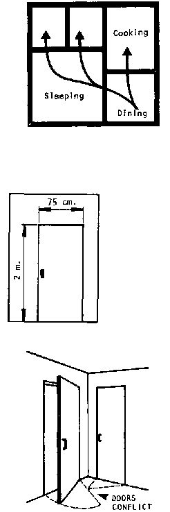
A community planning a clinic or school must consider many different needs. For example, a clinic would have to have space for treating patients, for people to wait before they are treated, and perhaps space for one or more people to stay overnight while recuperating. These would be the primary needs. However, the community might also desire to use the clinic for educational purposes: health education, for example, or nutrition classes. The most effective design would depend on all the planned uses of the building.
A family needs to plan enough space for all family members. The family must decide how many rooms they need, what kinds (dining, sleeping, etc.) and what size. Other needs may include ease of movement, storage space, privacy, etc.
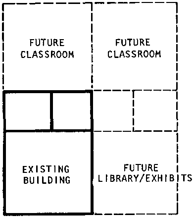
IS THE BUILDING DESIGNED WITH FUTURE NEEDS IN MIND?
Present needs may change soon:
� there may be many more students in the school 3 years from now; or the community may start holding meetings in the school next year;
� a doctor may move into the community and need living space near the clinic;
� a family may grow and need more room.
Future needs like these can be difficult to fill if the building is constructed next to something (like a river or road) that will block future construction; or if it is designed in a way that makes additions impossible. The easiest way to ensure that a building will be useful throughout its lifetime is to anticipate future needs and plan so that they can be filled easily by adding to the present design whenever they arise.
SITE SELECTION AND POSITION
In addition to a building's design, where it's located (the site) and which direction it faces (the position) are crucial to its success. Four factors must be considered in choosing the best site and position:
*location: Will a school, for example, be relatively easy for all students to reach? Can construction materials be brought to the site easily?
*terrain: Is the land hilly or flat? hard or soft? well-drained or marshy? subject to earthquake? All these factors affect building design, safety, and comfort;
*Size of the plot: Is there enough land for the building? Is there room for future additions to the building?
*Climate: The temperature, prevailing winds, and rainfall all affect the comfort and healthfulness of a building. And the position of a building is crucial in helping to control the environment inside the building.
Detailed Planning and Directions for Construction
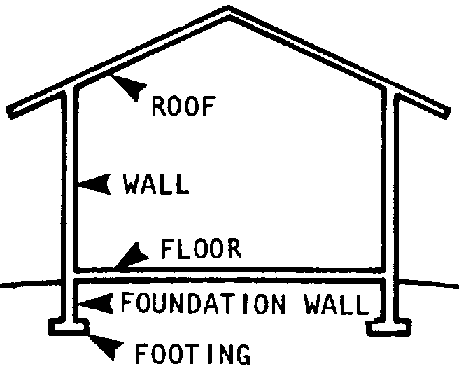
Buildings have 4 basic parts:
� footing and foundation
� floor
� walls, doors, and windows
� roof
Section 2 of the manual contains the information needed to draw plans for each of these parts. Section 3 contains step-by-step guides for the actual construction: that is, how to work from written plans to complete a structure that will last a long time and require a minimum of maintenance.
FOUNDATIONS
The foundation of a building provides a level base for the structure to stand on. It must be strong enough for the building that sits on it; it must be level and plumb (straight up and down); and it must be secure from damage by water, frost, settling earth, and earthquakes.
FLOORS
Floors provide a secure, level, and comfortable surface for everything inside a building. They must be far enough above ground level to remain dry, easy to keep clean, non-slippery, and level (so that objects do not roll or slide).
WALLS, DOORS, AND WINDOWS
Walls provide privacy and shelter from the elements. They also hold up the roof. They must be thick enough to protect the inside from heat or cold, strong enough to support the roof and withstand wind pressure, and high enough so that people can stand comfortably without hitting their heads on the ceiling.
Doors and windows provide light and ventilation. In addition, doors (or doorways) allow people to move in and out of the building and between rooms. They must be designed to allow only as much light, air, cold, and heat as desired into the building; at the same time, they must keep insects, dirt, and rain outside and provide privacy when closed.
ROOF
The roof protects a building from rain, snow, wind, cold or heat, and insects. It must be designed to withstand wind pressure, and the weight of anything that might fall on it. In addition, care must be taken to ensure that community members will be able to build the roof (the parts cannot be too heavy to lift).
Latrines
Latrines are important to good health because they can eliminate diseases spread through human excrement. They should be included in the planning of any public building or home. Special rules apply to their location, position, and construction. See Section 5, page 189.
Earthquakes
Earthquakes place severe stresses on buildings. But there are many methods of construction, principles of design, and materials that can help a building withstand tremors--at least long enough to allow occupants to escape safely. Most of these earthquake-resistant techniques cost nothing at all, or are very inexpensive. Builders in earthquake zones can and should use these techniques even when their budget is limited. See Section 6, page 195.
Before construction can begin--or detailed plans for construction can be drawn--the builders need to consider three basic planning and design questions:
SITE AND POSITION
� What land will the building be constructed on?
� Where on this site will the building be placed?
SIZE, SHAPE, AND FLOOR PLANS
� How many rooms will the family or community need?
� What size will each room be?
� How will each room be placed in relation to the others (that is, what will the floor plan be)?
� What shape will the building be? Round? Rectangular? Some other shape?
� How high will the ceiling be?
� Where will doors and windows be?
CONSTRUCTION MATERIALS
� What will the foundation and floor be made of?
� What will the walls, windows, and doors be made of?
� What will the roof be made of?
There are a number of simple guidelines that anyone planning a building can follow in answering these questions. But it is important to treat them as guidelines and not as hard and fast rules. There are rarely any "right" answers. Those who will use the building must be prepared to find compromises between their needs and budget on the one hand, and the limitations of local climate, soil, geology, and construction materials on the other.
This section of the manual is designed to help the field worker and community member(s) work together step-by-step to answer the three basic planning questions above for schools, health clinics, and homes. By following the process suggested, the builder will end up with an accurate picture of what his or her building will be like.
Families and communities need to decide carefully where they will build. They need to know their building's:
� SITE The plot of land the building will be on; where will the land be? what will its boundaries be? how big will it be?
� POSITION The exact position of the building on the site; which way will the building face? how far will it be from each of the site's boundaries?
Taken together, site and position are just as important as, if not more important than, how well the building is constructed. They can determine a building's safety, usefulness, and durability. In addition, a well-chosen site can significantly cut the cost of construction and maintenance.
At the very least, the site must be big enough for the building being planned plus at least some room around the building for the storage of construction materials during the construction. Generally, about 2 meters along each side of the building is the minimum builders will need. In urban areas, extra land may be required for health, safety, transportation, or other needs.
A major note of caution here: a site can only be truly adequate if it leaves enough room for present and future needs beyond the space taken by the main building being planned. These needs will be different for different types of buildings.
Here are some of the things planners might want to leave space for:
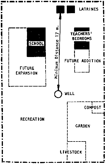
Schools
- a shaded outside area for assemblies, lunches, outdoor classes
- recreation area for sports, play
- future classrooms
- other additions such as offices, library, theatre, school garden
- compost pile
- livestock/poultry pens
- two or more latrines at least 17 meters from water supply
- cistern/well
- lodging for teachers
- storage for school and maintenance supplies
Health Clinics
- future additions for extra reception and treatment rooms
- cooking area for patients who must stay in clinic
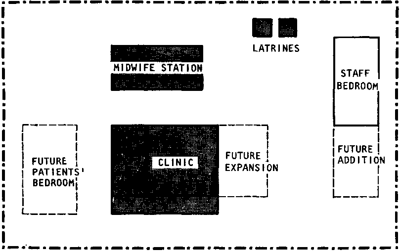
- latrines
- well
- lodging for health workers/ doctors
- separate building for maternity care and recuperation
Homes
- outdoor latrine
- garden
- livestock/poultry pens
- future additions to the home
- well
Many of these needs may appear farfetched to the family or community when they first plan their building project. However. the field worker should urge them to allow room for as much future expansion as possible. It is always easier to add to a present building and site than to start over again because there is no room at the first site.
Even in cases where the family or community cannot afford a large enough site for all future needs, they con consider what land next to their site might be obtained for later expansion.
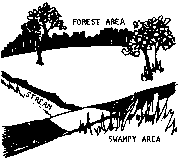
In addition to the actual size of the site, planners need to consider other conditions at the site that might block future expansions:
� rivers, streams
� heavy forest or bush
� unsuitable land (such as marsh)
� roads, markets, existing buildings
Whether these obstacles are on the projected site itself, or on the land next to it, care should be taken that they will not block the builders' present or future needs.
A building can only be easy to build and easy to use if the site is accessible; that is, if it is conveniently close to other people and places in the community and if it can be approached easily.
At the same time, a building can only be comfortable for those who use it if the site provides enough privacy to satisfy their needs. Privacy can also be important for health: for example, dirt, dust, and smells can cause serious problems if a building is too close to a heavily travelled road.
Because the need for accessibility often conflicts with the need for privacy, planners often have to compromise between them.
Here are the major considerations that may have to be balanced:
Access for Construction. Unless the materials for construction are available on the site itself, some or all of them will have to be brought to the site in large amounts. Generally, this means the site should be near a road, or in an area where a road to the site can be built. In addition, there must be space on the site to store materials during construction.
Access for Use. To serve its purpose well a building must be easy for people and supplies to get to. For different kinds of buildings different considerations should be kept in mind. For example: Schools should be
- within reasonable travel distance (by foot and/ or vehicle);
- close to clean water;
- close to fuel supplies in cold climates;
Clinics should be
- centrally located so that the community can reach them easily;
- close to clean water and fuel supplies;
- next to a roadway suitable for vehicles;
Homes should be
- close to clean water for cooking and washing;
- close to neighbors;
- close to fuel supplies;
- close to the family's fields or other places where the family earns income;
- close to markets;
- close to community facilities.
Privacy, Comfort, Health, and Safety. All building sites should be:
- away from rivers and streams heavily infested with mosquitoes, or other sources of disease;
- away from forest, bush, or jungle (all these cut off breezes, are dangerous in case of fire, and provide homes for snakes, rats, ants, and other pests);
- away from major roads and other sources of noise, dust, dirt, distraction, smells (this is especially important for schools and clinics);
- away from flood-prone areas;
- away from fault lines in earthquake areas (see section on earthquake areas, page 195.
Possibly the most important consideration in choosing any site is that the soil must be able to support any building(s) erected on it. Almost any ground can be built on (or over), but the nature of the site chosen will affect the simplicity or complexity of the foundation, the cost of construction in labor and money, and the durability of the building.
� Rocky soil provides the strongest support for a building, usually much more than is necessary for a 1-story building. But while it is extremely stable, it can be very hard to excavate.
� Hard-packed clay is generally the best soil for 1-story buildings: strong, but easy to work with.
� Sand and gravel are usually acceptable soils for 1-story construction. They can support about half as much weight as clay, but they are subject to shifting or slipping, especially if the site is not on level ground.
� Soft black soil, drained marshland, and "made" earth (fill that has been collected and packed) are satisfactory soils for construction. However, buildings constructed on these soils should be built on concrete foundations, or on raised platforms. In addition, buildings on these soft soils should be made with the lightest suitable materials available. Black topsoil contains decayed organic matter that makes it soft, especially when moist. In areas where such soil goes more than 30-45 cms. deep, it must be removed before construction can begin. Otherwise it will almost certainly shift under the foundation and lead to wall cracks or collapse of the building.
Each type of soil has very definite limits to the weight it will support. Generally speaking, 1-story buildings will be well within those limits except in the case of buildings with rock walls on the weaker soils.
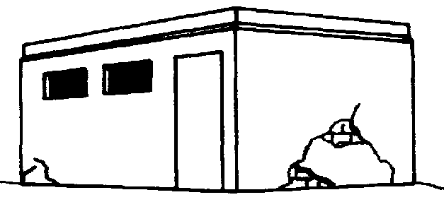
When a tentative site has been selected, it's a good idea to double check that the soil at the site will support the planned building safely. Quite often this can be done simply by looking at similar nearby buildings (2 or more years old) on the same kind of soil. If they show signs of uneven settling such as cracks in the walls or foundations, the side of the new building may have to be dug out and filled with firmer soil, or another site may have to be selected.
In cases where there are no similar buildings nearby, or no similar soils, an estimate of the planned building's weight per square meter should be made and compared with the weight-bearing capacity of the site. Detailed directions for calculating the weight of a building, plus a guide to the weight-bearing capacity of various soils will be found in Appendix 1.
Almost as important as the type of soil at the site is the uniformity of the soil. If the ground at the site contains a mixture of different soils, it must be dug out and filled in until it is uniform in order to provide a stable support for any building.
If the ground at the site cannot be made uniform, or if the weight of the planned building will be close to the weight-bearing capacity of the site, it may be necessary to use reinforced concrete in the foundation.
In addition to the weight the site can support, builders need to consider how well the land is drained. Water seepage can destroy even the strongest foundation if it is not controlled or planned for. Wet or damp floors can make a building uncomfortable and unhealthful.
Whenever possible, marshland or any ground that lies underwater for extended periods of time should be avoided for construction purposes. In some areas, people have developed methods for construction on stilts because they have no access to dry land, or because they depend on access to the water for economic support. Buildings in these areas should be made of light materials and should be replaced often.
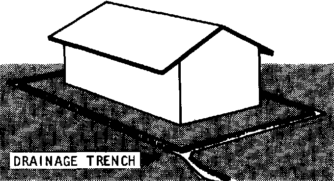
Low-lying land, and land that may be exposed to short-term flooding is also less than desirable for construction purposes. When there is no choice, however, this kind of land can sometimes be improved by digging a trench about 25 cms. wide and 10-15 cms. deep around those sides of the building site that won't drain. These trenches should lead far enough from the planned position of the building to keep water from rising to the foundation depth.
If the dark topsoil in low-lying areas is more than 30-45 cms. deep, every effort to find a different site should be made, since removing this topsoil for a firm foundation will be expensive and can make effective drainage much more difficult.
High, dry ground is usually the best for building sites since it is not subject to the ill-effects of water seepage. However, ground can be too high. Planners need to avoid or guard against these dangers:
� if the ground is also hilly, the excavation needed to produce a level area for the foundation may be too difficult or expensive;
� if there are heavy rainfalls, rapid drainage may cause erosion, ground slippage, or landslides that can cause a building to collapse or can bury it; in most cases, a retaining wall and carefully planted trees can solve these problems, but both alternatives can be expensive;
� if high ground is exposed to high winds or storms, the building may be in danger of collapse, or it may lose its roof.
The ideal site for any building is on dry soil safe from flooding and sheltered against ground slippage, strong winds, and storms.
After selecting a site, the builder needs to decide where on the site the building or buildings planned will be. The position that is chosen should ideally:
� be far enough back from the site boundaries for privacy and comfort
� leave room for future additions
� leave sufficient room for storage of construction materials
� allow the windows and outside doors to face as close to north and south as prevailing winds will allow (see the section on windows and doors, page 52)
� be as level as possible
� be as dry and strong as possible
� be away from forest, brush, or jungle area on the site
� conform to all local legal regulations.
The most important factors community groups and families should consider in choosing a site for their building are:
� whether the soil will support the weight of the building;
� whether the site is drained well-enough to prevent water damage;
� whether the site is large enough to accommodate their immediate and future needs;
� whether the site is easily accessible for construction and use of the building;
� whether the site is comfortable, safe, and healthful.
In most cases, builders have to compromise between these concerns. Choosing the best site among several less-than-ideal possibilities is often difficult and complex. It is always best to get experienced advice, whenever there is any doubt. Contractors, engineers, or architects in the area can help make the options clear, especially in terms of cost and labor.
One Final Caution. In many areas, local regulations will influence what can be built, where it can be built, and how it can be built. Building and zoning codes, permits, licenses, and accepted practices vary widely from country to country and locality to locality. To avoid wasted or illegal effort, the field worker should help family or community members learn their restrictions and obligations during the basic planning and design process. This should always be done before settling on a definite site for construction.
Generally, the smaller a building, the less it will cost to build. So the first aim of any community group planning a new building should be to decide what their minimim space needs are. If they can afford more than the minimum, it will be easy to add room before construction plans are final.
Small community schools are generally simple to design. For indoor classrooms, plan a minimum of 1.3 square meters per student.
For example, in a 1-room school for 30 students (the most that should be planned for in one class), you would need about 30 x 1.3 = 39 square meters for seating. Add to this about 2 meters in front for a chalkboard and teacher's desk/table.
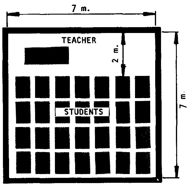
Classrooms for fewer students can be smaller as long as there is about 1.3 square meters per student for seating and about 2 meters across the front for the teacher. However, if the community can afford it, it is a good idea to build every classroom at least 5 x 8 meters. The extra space will come in handy for exhibits, special projects, and extra students if class size increases.
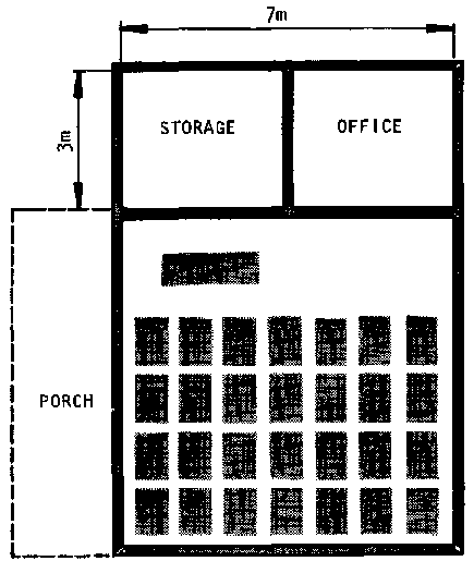
It more storage and/or office space is required, add it on the end of the school.
If there will be more than 1 teacher, the plans should include one room for each teacher and his/ her students. The additional classrooms can be added as needed next to the first.
If the community plans to use the school as a public meeting room, thought should be given to making the first classroom larger than needed to accommodate large adult groups. Or, a large assembly room might be built specially for the purpose and attached to the class for use as a theatre.
Many communities, especially in the tropics will want to plan a shaded porch for use in very hot weather.
Don't forget to plan for latrines and a water supply on the school grounds (see section on latrines for special rules that apply to the location and number of latrines).
If needed or desired, thought should be given to space for a school garden, lodging for teachers, and sports.
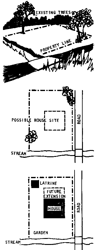
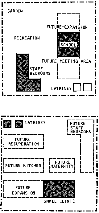
Here is one possible site plan including these features:
Health clinics usually require more advance planning than schools to fill a community's needs well, because separate rooms are needed for the reception and treatment of patients, care of patients who must sleep in the clinic, and space for office and supplies. In addition, latrines should be included in the plans for any clinic (see separate section on latrines for detailed planning).
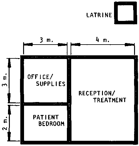
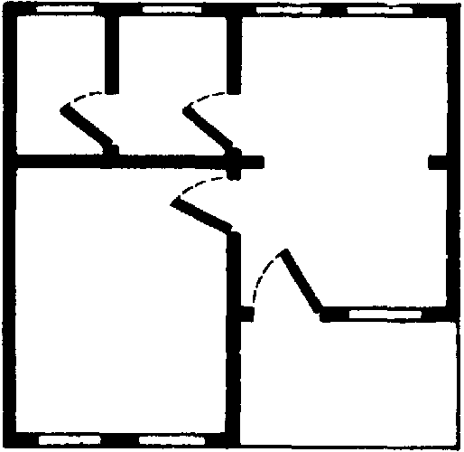
This is a floor plan for a small health station, with 3 rooms and 2 inside walls, measuring 7 X 5 meters.
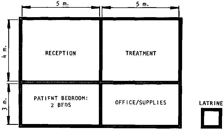
A more complete clinic might be twice the size, 7 X 10 meters. To reduce noise that may disturb in-patients, and to reduce the possibility of infection, patient rooms should be as far as possible from treatment rooms.
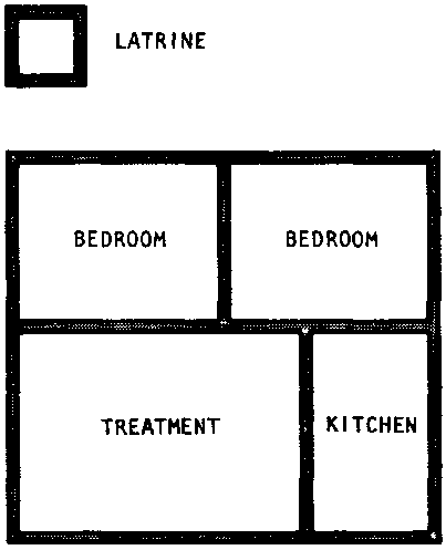
A desirable addition to one of these clinics would be a midwife station in a separate structure on the same site.
Midwife stations permit special care for mothers and babies during and after delivery, without exposing them to infection from clinic patients.
Here is a possible plan for a midwife station.
This is a SITE plan for a complete health clinic.
In normal times, housing projects are more difficult to organize than community projects such as schools and health clinics. But after a disaster, such as an earthquake or flood, many people are in urgent need of new homes---at a time when they may be least able to afford construction or to think carefully about their new home's design without help. As a result, many agencies providing disaster relief have tried to design and build new homes for people ---only to find that the new homes stand empty because people don't like them. This problem can be avoided if field workers use the ideas suggested in this section to help families plan their own homes.
As with schools and clinics, the smaller a house, the less it will usually cost to build.
Here are some guidelines to help a family decide what their minimum needs are:
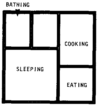
� The plans for a house should clearly show where each of the family's basic activities will take place. Even the smallest home must have adequate space, either inside or outside, for the family to sleep, cook, eat, and move around in comfort.
� In addition, the family should consider including space in its plans for a latrine and a shower. Latrines are especially important for every family's health. They can be designed as part of the main house itself. But there are several advantages to building latrines as separate structures on the same plot of land. For example, an outdoor latrine can be moved easily when it fills up.
� Other activities a family may wish to plan space for include laundry, prayer, and private space.
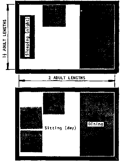
� When cost is a critical problem, a family can save money by using rooms to serve more than one purpose: for example, a single room can provide living and eating quarters by day, and sleeping space by night.
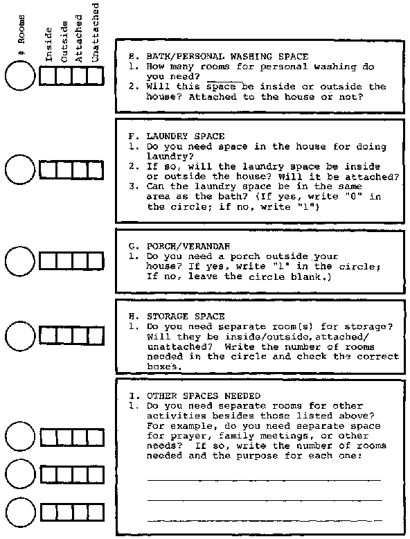
The following questionnaire can be used to help a family determine what kind of space they need and how many rooms they need to build.
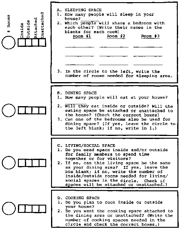
Check over your answers to these questions. The information you've listed should help you decide exactly how many and what kind of rooms/spaces you need to plan.
To be useful and comfortable, a room must be large enough and properly shaped for its function. For example, a bedroom must be long enough for a person to lie down in and wide enough so he or she can get out of bed and in and out of the room easily. A latrine, on the other hand, only needs to be large enough for a person to sit or squat (unless people also plan to dress or wash in the same area).
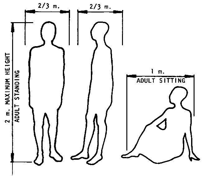
The best way to make sure that a room will be large enough is to decide how large it would have to be for the largest adult likely to use or visit the home. Then the room will be comfortable for everyone.
[Note: Often the proper size and shape of a room is determined more by traditional requirements and social patterns than by physical comfort. Field workers must be sensitive to the community's needs and priorities and should explore them thoroughly with the family.]
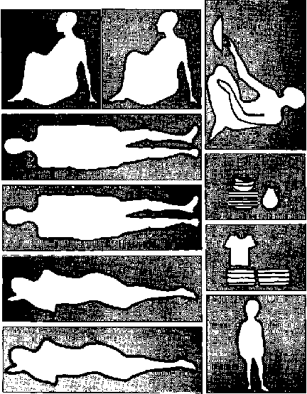
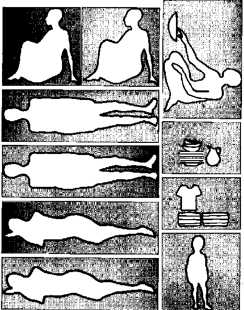
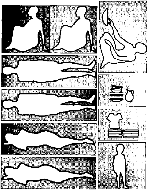
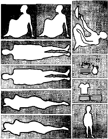
Here are some guides for a "human" measuring unit:
- Most adults will be less than 2 meters tall;
- An adult usually needs 2/3 meter from side to nice and from front to back in order to move around; and about 1 meter, or nearly half his/her height to sit down.
A family's interest and confidence in a building project will be much greater if they are able to envision and plan their home's rooms themselves. A first and very important way the field worker can help them do this is to visit other homes in their community with them and question them carefully about their reactions. Some questions a family might want to ask include:
� Do we want our rooms to be larger or smaller than these?
� Would we like them to be the same or a different shape?
� How do we feel about rooms with more than one purpose (for example, sleeping, dining, and living)?
� Are the rooms we have seen easy to move around in, or difficult?
� Is working in the kitchen or laundry space easy, or does it take a lot of walking back and forth?
� Do family members get in each other's way when moving from room to room? Where and why?
Once the family is familiar with a number of different possible designs, they will need to put the actual size and arrangement of rooms in their new home on paper.
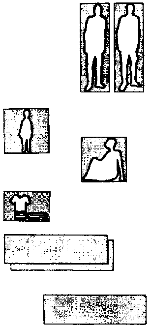
An easy way to help them get started is to give the family pieces of paper representing the "human" measuring unit. Using 12 cm. for 1 adult length is the most convenient scale since 1/2 adult is an even 6 cm. and 1/3 adult is 4 cm. The family will need pieces for:
* the length and width of an adult standing or lying down;
* the length and width of an adult sitting;
* the space an adult needs from side to side in order to walk or work comfortably.
* any furniture they have or special space needs (for example, in countries with cold climates, space may be needed for chamberpots in the bedrooms so people don't have to go out at night).

Remember that the pieces must be proportional to one another so that they can be used to get an accurate picture of the space needed.
NOTE: Extra copies of the planning pieces for use with a community group are provided in Appendix 8.
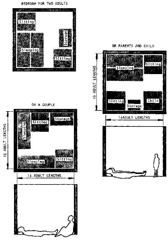
A family can design its own rooms by gathering pieces it needs for any room and then arranging them into a square rectangle, or circle.
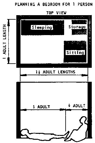
For example, a family planning a bedroom for a couple and one child would need:
� 2 pieces of an adult length and width for the couple's sleeping area;
� 1 piece �-length x �-length for the child's sleeping area;
� 1 piece �-length x �-length for an adult to sit;
� 1 strip the width of an adult for clothing or storage;
� 2 strips the width of an adult for each parent to walk around their bed(s), and to walk to the baby's bed;
� extra pieces for large furniture or other needs.
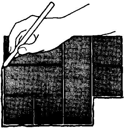
Once the pieces are gathered, the family should try to put them together so they form a room-shape. There are many combinations possible for any room, so people should be encouraged to experiment with as many arrangements as possible.

When all the pieces have been placed together, a line should be drawn around them. This line represents the complete room
If the shape of the room is irregular, the field worker should help the family make adjustments until it is a simple shape.
Space can be added to complete a square, rectangle, or circle. Some of the space in walking areas can be carefully reduced by up to 1/3.
To find out what the dimensions of the final room should be, first calculate the number of adult lengths along the sides of the room.
Then the family, or the field worker, if necessary, should multiply the number of adult lengths by 2 meters.
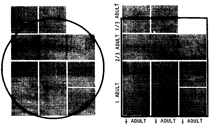
The answer will equal the actual dimension of the wall in meters.
EXAMPLE: Calculation of Dimensions of Rectangular Room Above
Width:
� adult length
� adult length
� adult length
1� adult lengths x 2 meters = 3m
Length:
1 adult length
2/3 adult length
1/3 adult length
2 adult lengths x 2 meters = 4m
Room Dimensions: 3 meters x 4 meters
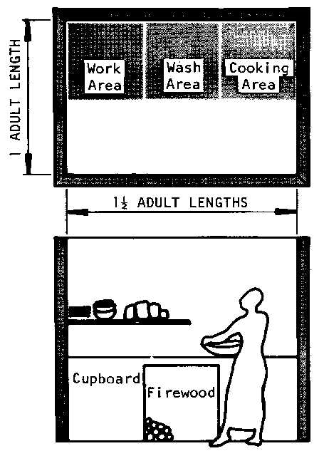
Here are some additional measures that may be useful in deciding what pieces the family must use in planning kitchens (or outdoor cooking areas), and dining areas:
� Work space in kitchens, especially counter space should be about 1/2 adult wide. Anything wider will be hard to reach across;
� Space for fuel in kitchens should be about 1/2 adult long by 1/2 adult wide;
� Dining space for each person (that is, space for the person to sit and space in front of him or her to eat) should be about 1/2 adult wide and 3/4 adult long.
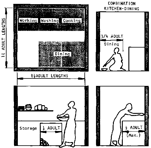
Let's look at how the "human measuring unit" can be used to plan several rooms. These suggested plans may be useful if a family has problems picturing what they can do with the "pieces" for a room. ( Note: the field worker may want to adapt these illustrations if the furniture shown here is not relevant to the local area)

Kitchens may be inside or outside, but in either case, they must be big enough to store all utensils and food away from animals, and to provide working space; at the same time, they should be small enough so that everything can be reached easily without many trips between supplies.
Shelves and cupboards save floor space. In places where the kitchen is primarily for storage and most of the cooking is done outside, the kitchen can be smaller.
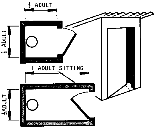
Latrines can be small: 1 m. X 1 m. However, if they are built longer, they will be easier to clean and to move around in. (See the separate section on latrines, page 188 for more details).
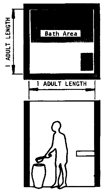
Bathrooms require room to shower or bathe, to dry oneself, and to get dressed.
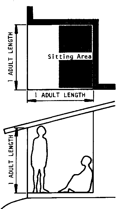
A verandah, or porch, is really a room with 2 or 3 sides open to the air. It should be big enough to be comfortable for social gatherings, family, prayers, or other meetings; this means at least one adult wide and one adult long (longer for large groups), so that there will be room to sit or lie down, and to walk around anyone using the room.
When the number and size of rooms needed have been determined, the next step is to decide how they should be put together to form the house.
The easiest way to do this is to draw a picture of how the rooms would look from above if the roof were removed. Since it shows how the floor-space in the home will be divided among the rooms, such a picture is called the floor plan.
One thing to keep in mind when designing a floor plan is to keep the shape of the building as compact and simple as possible. Odd shapes and sharp angles are more difficult and more expensive to build than either rectangles and squares! Curves are also expensive except when bamboo, or similar materials are used.
As in planning room size, the family's interest and confidence in a building project will be greater if family members participate in the drawing of their own floor plan.

The field worker can help them draw the plan by giving them scale model pieces of paper or cardboard representing the rooms they have planned and helping them arrange the pieces in several different "floor plans".
Each possible floor plan should be discussed at length in order to determine how well it will fit the needs of the family.
When a final decision has been reached, the arrangement of the room-pieces can be copied on a single sheet of paper. This paper then becomes the floor plan.
Here are some step-by-step examples of how the floor plan for a small family's house might be developed.
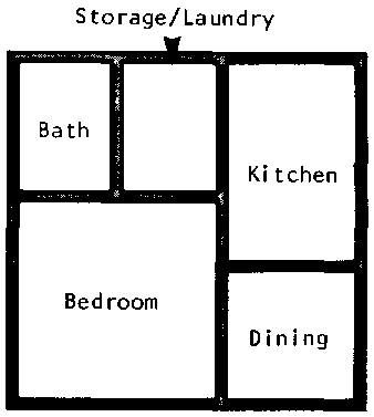
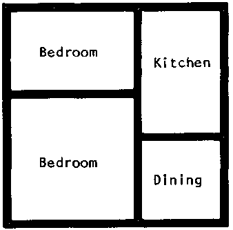
Sample Plan #1: House for a couple with no more than 1 child
A good way to start a floor plan is to place the piece for the main bedroom (the room where the heads of the family will sleep) in the center of a sheet of paper.
For a couple with no children, this might be the bedroom suggested on page 37. This size has the advantage that a first child could be easily accommodated without cramping.
To this bedroom might be added a kitchen and a living/dining area (both kitchen and dining area are shown indoors here; if either or both will be outdoors, the space required may be very different).
At this point doors have not been shown in the illustration.

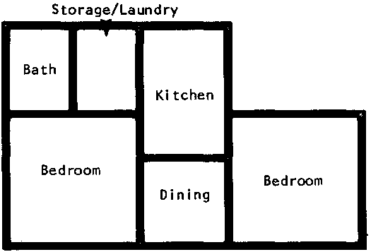
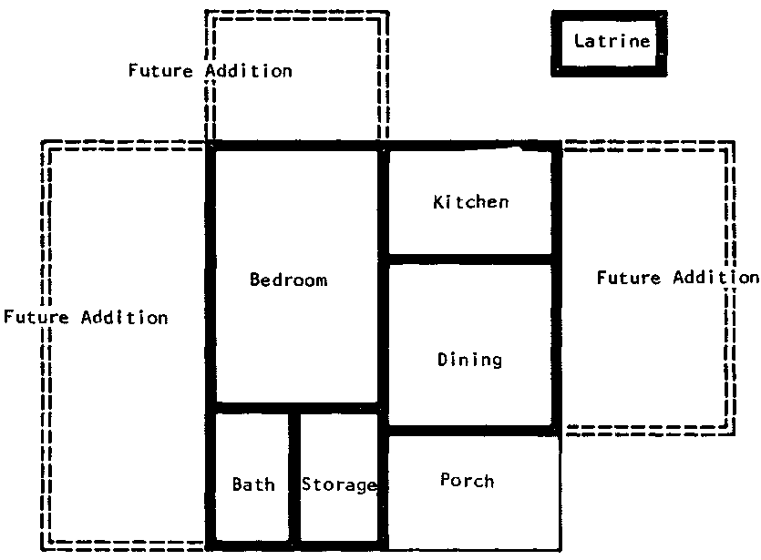
The home could be built on this plan. But any of several changes or additions to complete the square are possible. If grandparents or aunts and uncles are part of the family, they may require the main bedroom; in which case, a second bedroom would be needed.
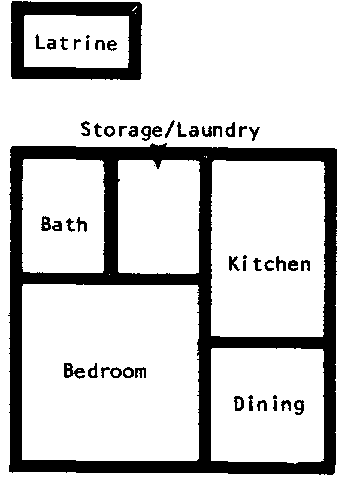
In a nuclear family, a shower can be added, along with some storage or laundry space to complete the square:
Or, the same space can be used as a porch:
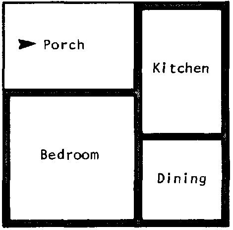
Finally, a latrine should be planned near the house, preferably where it will be sheltered from public view,
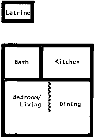
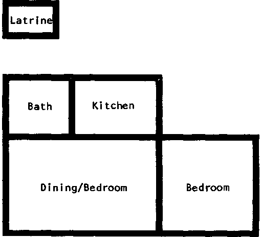
Sample Plan #2: House for a couple with no more than 1 child.
A less expensive alternative for the same couple would be to build a single bed/living-dining room using a screen to separate the two areas instead of a wall:
Sample Plan #3: House for a Small Extended Family or A Couple With 2-3 Children.
To design the floor plan for a slightly larger family, all the planner needs to do is add a new bedroom to the smaller homes shown in Plans#1 and #2.
For example, the verandah in Plan #1 could easily be remodeled as a bedroom for two children or an aunt and uncle:
Plan #1 could also accommodate a new room either next to the dining room, the first bedroom, or the shower:
In Plan #2, the original bedroom can be converted into a room for two children or grandparents, and a second, smaller room for the parents could be added on the other side of the kitchen area.
Sample Plan #4: House for a family of 4 or 5.
Here's another plan for a family of 4 or 5 that could be added to if the family continued to grow:
Some Points to Remember About Floor Plans.
� The kitchen and dining areas should always be next to each other so that food can be carried easily from one to the other. If dining will be outside, the kitchen should have an outside door.
� In countries where privacy is important, each bedroom should be planned with separate access to baths and/or indoor latrines, so people won't have to pass through someone else's bedroom.
� In many countries, standard floor plans for various size homes are available from the government or local architects and engineers. But check to be sure that these plans are appropriate for lower income family needs!
� A good way to find out what makes a good floor plan is to explore homes in the local area and copy or adapt successful ideas. Such a survey can be especially helpful in planning so that family members will not get in each other's way when moving about the house.
No floor plan is complete until it shows where the inside doors between rooms will be placed and how people will move from room to room. (For outside doors, see the guidelines for windows and special notes on page 65.
Inside doors should be designed to:
provide easy movement between rooms;
provide privacy (if desired).
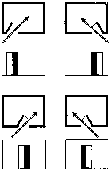
Easy Movement depends primarily on the size of the doors. They should be one adult high, or 2 meters, and at least 75 to 100 cm. wide for all rooms except bathrooms, which can have narrower doors, 60 to 75 cm.
One other factor that can affect ease of movement is how close doors are to other parts of the house. Doors should be placed so that they don't interfere with other doors, open windows, or major pieces of furniture (such as beds).
Privacy depends on how much of a room can be seen through the doorway. There is no problem when the door is closed. However, it is often desirable to leave the door open for air circulation. Privacy can still be maintained if the door is placed properly and opens in the right direction.
The chart on the following page shows the right and wrong ways to place doors in a room.
Door Placement.
Doors should be placed--and hinged--so that as little as possible of the inside of the room is seen when the door is open.

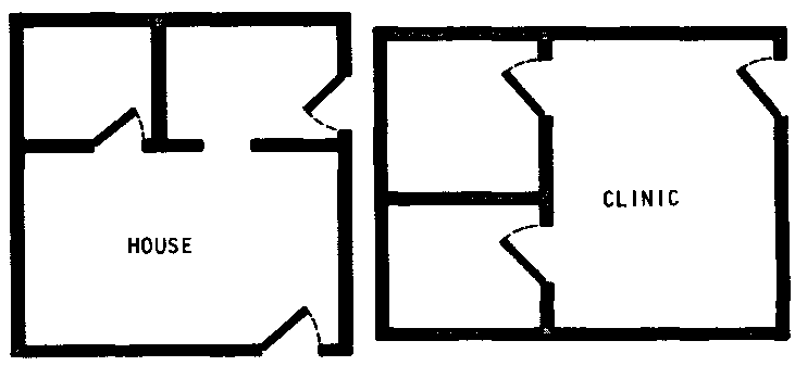
Doors are shown in floor plans by drawing a line representing the door in the open position.
Here are some examples of how doors might be shown in the floor plans we've already seen:
Ceilings must be high enough so that people can stand up comfortably. The best rule to follow is to keep the ceiling about 1/3 meter above the doors, or about 2 1/3 meters high.
If ceiling lights or fans are planned, then add about 2/3 more meters to make the ceiling at least 3 meters high.
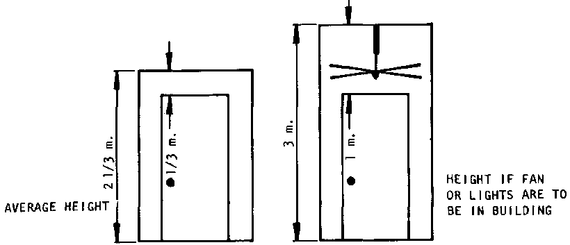
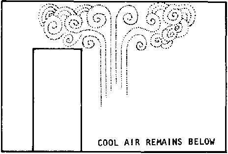
In tropical areas, higher ceilings are significantly more comfortable if they are ventilated to allow heat to escape. Buildings with unventilated high ceilings tend to be very uncomfortable because heat collects in the space above doors and windows, making it difficult to keep the rooms cool.
Avoid high ceilings in cold weather areas: they make rooms harder to heat because the warm air from people, fireplaces, or heaters rises to the ceiling where it cools off before it can warm up the living area.
Most windows do the following things, in varying degrees:
- they aid the circulation of air in the building;
- they provide light (and warmth, in the daytime);
- they provide a view of the outside (and they also allow outsiders to see in).
At the same time, windows can do the following things, or fail to do them:
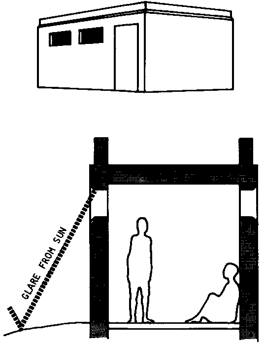
- protect from too much wind, rain, heat, and glare;
- help keep the house cool;
- ventilate enough to control mildew and molds.
The best size, design, and placement of windows for any building depends on how much light, heat, and wind is desired inside. So the most important consideration in planning windows is the climate. Generally, the best way to design windows is to survey the windows in nearby buildings and use ideas that have worked well in local conditions.
But there are some general guidelines the field worker can follow in advising a community group or family. Here are two typical climates and what you would want to achieve in each:
|
Climate |
Windows should be designed to: |
|
Tropical |
- avoid heat from the sun; |
|
- protect inside of the building from rain and insects; |
|
|
- take advantage of any breeze day or night. |
|
|
Desert |
- avoid heat from the sun; |
|
- protect inside of the building from dust; |
|
|
- protect inside of the building from wind, especially at night. |
Avoid Heat from the Sun.
Two things can be done to avoid too much heat from the sun:
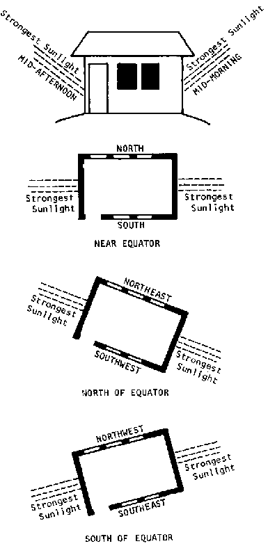
* windows can be placed so they face away from the mid-morning and mid-afternoon sun:
- near the equator, windows facing north or south will absorb the least heat;
- north of the equator, windows facing northeast and southwest will absorb the least heat;
- south of the equator, windows facing the northwest and southeast will absorb the least heat.
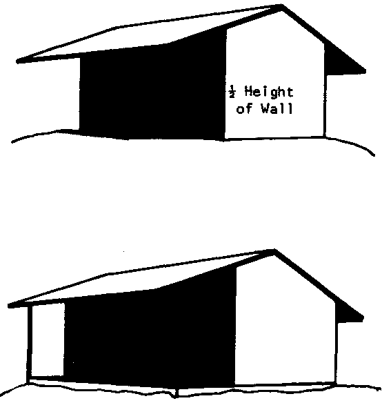
* Windows can be shaded:
- with full or partial shades built around the outside of the building;

- with the overhang of a roof; (the overhang should be half the height of the wall)
- by a porch; a porch serves as an open air, shaded area for rest, dining, and social gathering while at the same time protecting the windows and building from the sun.
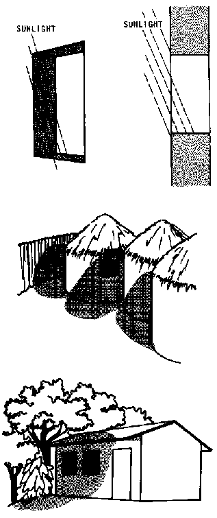
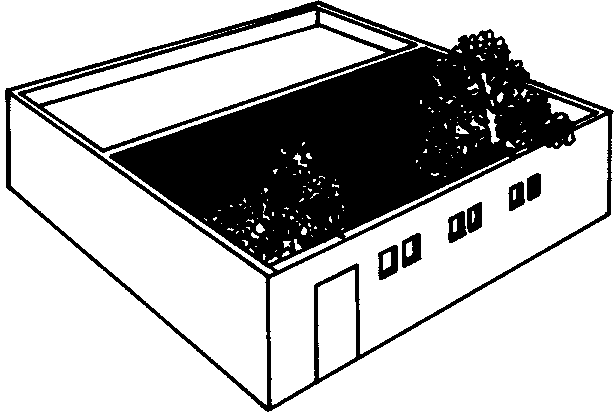
- by designing them as thick self-shading walls;
- by a shaded inner courtyard;
- or by trees or other plants.
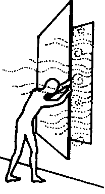
The best protections against bad weather and insects are outdoor shutters and screens. Shutters and screens can both help protect the building from animals and thieves
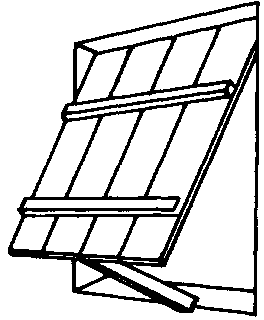
A variety of shutter designs can be used alone or in combination. The best combination in the tropics is usually a mesh screen (for insects) with a glass, wood, or well-made bamboo or reed shutter (for rain). The illustrations on this page and the next show several shutter and screen designs, along with their uses.
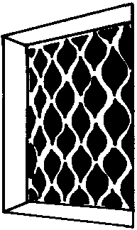
Mesh Screen
� lets in some light, heat, cold and dust
� keeps out insects, some light and some breeze
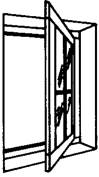
Glass
� lets in light and heat
� when closed, keeps out cold, wind, rain, dust, and insects
Fixed Screen
� lets in some light, fresh air, heat breeze, and insects
� keeps out some light, glare, sun

Reed Screen
� woven pattern slides over at night
� lets in some light, heat, cold, and insects
Solid Wood
� lets in heat, light
� keeps out some light, cold, wind, rain, and when closed, dust and insects
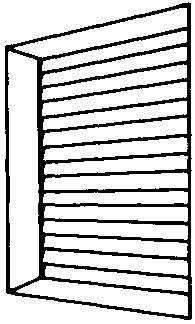
Louvered
� lets in some of everything
� when closed, keeps out wind, rain, dust, and insects

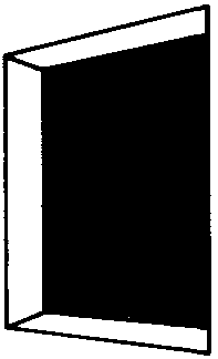
Double-door Shutter
� when open lets in everything
� when closed, keeps out everything
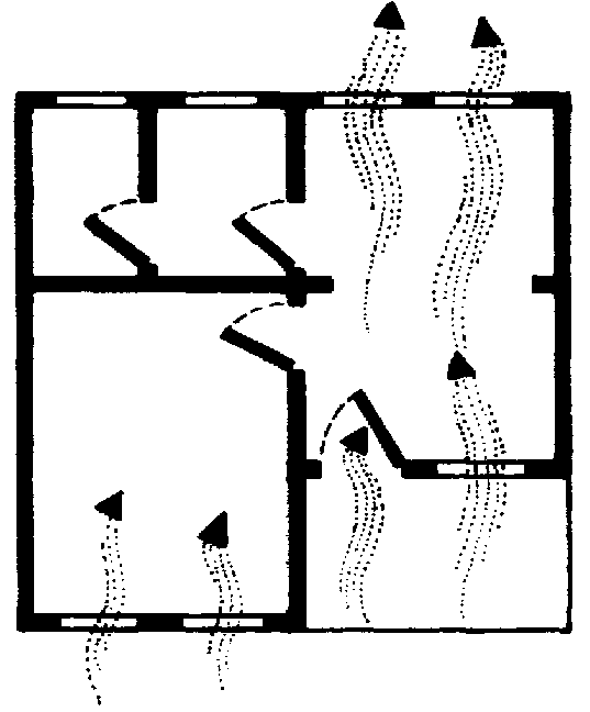
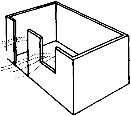
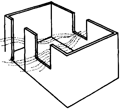
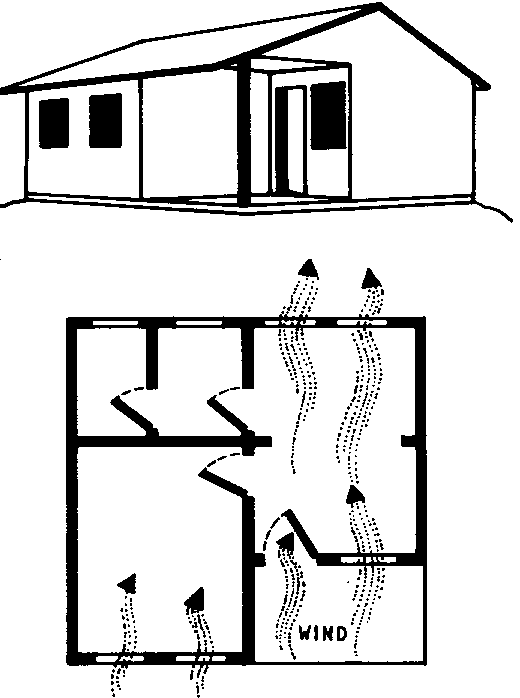
For noticeable circulation, there must be windows on more than one wall.
The building should be placed so that the windows face into light breezes, but away from harsh winds, and also away from the midmorning/mid-afternoon sun.
Here are six situations showing how buildings in the tropics should be placed depending on the direction of prevailing winds and the position relative to the equator.
NORTH OF EQUATOR
Northeast or Southwest Winds.
Windows face North and South to catch breeze and avoid sun as much as possible.
All Other Winds.
Windows face Northwest and Southeast to avoid sun and catch breeze as much as possible

NEAR EQUATOR
Due East or West Winds.
Windows face North and South as much as possible to avoid sun, but they catch breezes.
All Other Winds.
Windows face North and South to avoid sun, and catch breeze.
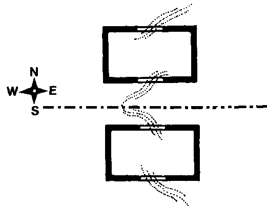
SOUTH OF EQUATOR
Northwest or Southeast Winds.
Windows face North and South to catch breeze and avoid sun as much as possible
All Other Winds.
Windows face Northeast and Southwest to avoid sun and catch breeze as much as possible.

Another way to increase circulation is to use as many windows as possible. But bear in mind that:
- building windows can be costly in labor as well as materials;
- walls facing mid-morning or afternoon sun should not have more than one window per room (so as to reduce heat from the sun).
The size of windows also affects circulation because larger windows allow more air in and out.
Again, some cautions:
- the larger the window, the more expensive it will be to build;
- since there most likely will be times when the windows must be closed with shutters, they should not be much bigger than about 1 X 1 1/3 meters. Anything larger may put too much of a strain on the hinges and make the windows difficult to open and close;
- large windows offer less protection against thieves or animals.
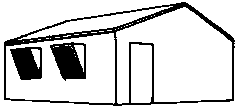
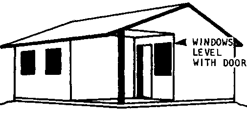
One final consideration in getting the most circulation possible is the height of the windows. Most windows in tropical areas should cover the upper half of the wall so that any breeze will be felt around the head and shoulders. A few additional windows covering the lower half of the wall, especially in sleeping areas, will further increase circulation.
Construction will be much simpler later if the tops of windows are kept level with the top of the door (about 2 meters).
To sum up, a good plan for a building in a tropical climate would have:
- windows facing away from the mid-morning and mid-afternoon sun;
- shades, overhanging roofs, or a verandah;
- several windows, placed opposite each other so wind can flow through the building (but no more than one on walls facing mid-morning and mid-afternoon sun);
- large windows covering as much of the upper half of the walls as possible plus a few windows in the lower half of the walls, especially in sleeping areas, (make sure they are not too large or heavy to open and close easily)
- screens to keep out insects, and shutters that can be closed to keep out rain, wind, dust, animals, and thieves.
Avoid Heat from the Sun.
The same rules apply to windows in desert-like areas as apply to windows in tropical areas.
Windows should be placed to avoid direct sun in the mid-morning and mid-afternoon.
Buildings in desert-like areas are often built around open courtyards shaded by trees and the walls of the building itself, so that windows open onto cooler air (the same idea is used in tropical areas, too, but less often).
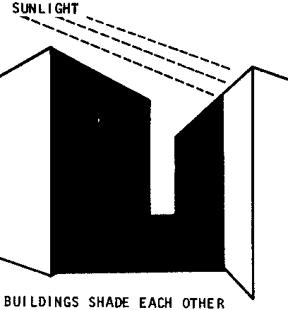
Buildings can also be placed close together so that each shades the walls and windows of the building next to it. This may block some breezes, but since winds in the desert tend to be hot and uncomfortable, it isn't so important to keep buildings open in them.
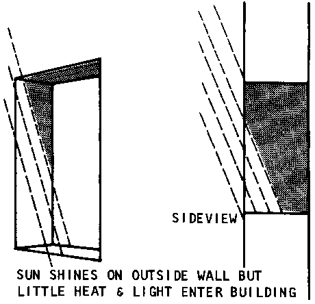
Windows in desert areas can also be protected from the sun's heat by designing them as openings in thick, self-shading walls.
Protect Windows from Uncomfortable Winds.
Since some desert winds are hot and uncomfortable, people want to be protected from them rather than exposed to them.
On the other hand, a building with no circulation at all would be uncomfortable and unhealthful.
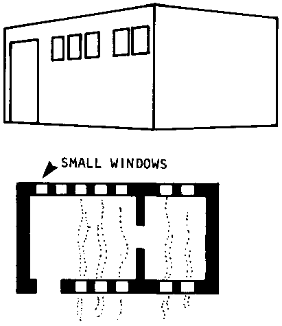
The best way to protect against uncomfortable wind without cutting circulation entirely is to plan small windows opposite each other.
Protect Windows from Dust and Glare.
In many areas, the ground tends to be dusty. In addition, because it is often bare and light in color, it reflects sunlight in strong glare that can be very uncomfortable.
Both dust and glare can be effectively guarded against by placing small windows high up from the floor. This prevents most of the dust picked up by winds from getting in, and blocks all the glare.
To sum up again, a good plan for a building in a desert-like climate would have:
- windows and doors facing away from mid-morning and mid-afternoon sun;
- small, deep-set windows to protect against hot winds and direct light;
- windows placed high to protect against glare and dust.
Like windows, exterior doors should be designed with climate in mind:
� they should be placed to avoid heat from the sun;
� they should be shaded from rain if they open outward, or they should be designed to open inward (otherwise weather will spoil the wood or bamboo and cause the door to twist, warp, or rot);
� generally it is worth the expense to shade doors so they can be opened outward since this is safer in emergencies such as fire or earthquake, and increases the amount of useful space in the building;
� in earthquake areas, outside doors should be placed close to the center of the wall's length (see the separate section on earthquakes (page 196).
Schools, clinics, and homes can be built out of an almost endless number of materials.
The proper choice of materials depends on almost as many considerations, including:
� the climate: some materials cannot withstand large rainfalls;
� the part of the building (floors, walls, roof, etc.): some parts need to be stronger than others;
� the builder's budget: some materials are much more expensive than others for original
construction, maintenance and future additions;
� the number of people working on the construction: some materials require many more people than others;
� the amount of time available for construction: some materials take months to prepare properly.
For any application, there are usually several materials to choose from that will be within the budget, time, and labor limits of the builders. Whenever there is a choice, the most important consideration is what materials (and equipment) are available at or near the site. Local materials are almost always less expensive, more acceptable to the people who will use the building, and more familiar to those doing the construction.
This section is designed to review basic information about the most common materials that small rural communities are likely to find nearby. Detailed directions in the use of these materials will be found in later sections covering the actual construction process (pages 115-180),
But once builders know the major characteristics of the materials discussed here, a brief survey of what is locally available will usually be enough to decide what to use.
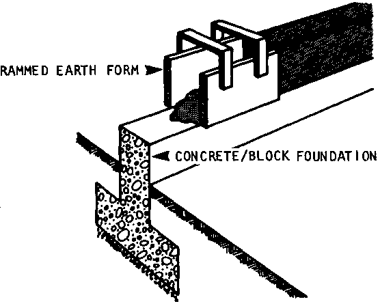
Rammed earth is a combination of sand, silt and clay that when properly pressed and dried is suitable for walls in dry climates. (wet climates, too, when protected with lime plaster.) If the sand, silt, and clay are locally available, rammed earth and adobe blocks are two of the least expensive materials to use.
Basically, the ingredients are mixed with water in this ratio by volume:
� 50 to 80% sand (the most important);
� up to 30% clay;
� 15% silt (extremely fine-ground rock).
The amount of water needed varies considerably and must be determined by making several tests. There should be enough to make a mud that holds its shape but can still be molded,
Once the ingredients are mixed thoroughly, they are pounded with a thin pole into a portable mold (form) 2/3 to 1 meter high until they are packed solid.
The mixture is then allowed to cure (dry) thoroughly. When one section is ready, the mold is removed and used to form the next section
Adobe bricks are individual solid blocks made from the same mixture of ingredients as rammed earth.
A simple form - or mold - is used to shape the bricks, which must be dry for at least a month before use. Because of the drying time needed, adobe bricks can only be used where there is a long season of hot dry weather.
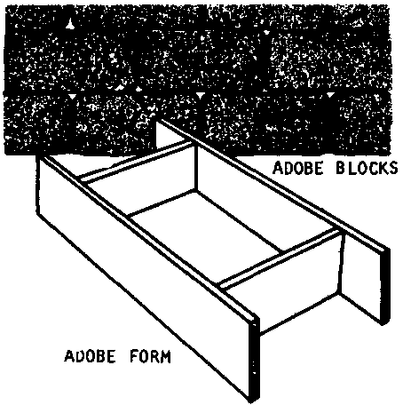
Construction with either rammed earth or adobe is inexpensive and highly labor intensive. This makes both materials especially good in low-income communities that can contribute volunteer labor
Rammed earth and adobe should never be used underground for foundations, since underground moisture will eventually weaken them. Both materials are excellent for walls, however, and can withstand rainfall if protected with lime plaster,
In earthquake areas, rammed earth and walls must be reinforced with wood, wire, or bamboo.
Finally, rammed earth and adobe structures cannot support heavy roof loads without strong wood or iron reinforcement. Light roof materials, such as thatch or bamboo, are the best to use with either rammed earth or adobe brick walls.
Wood is one of the most versatile and durable construction materials. It is easy to work with and can be used to build almost any part of a structure. Due to deforestation of many countries, however, wood is too scarce and expensive for use by most low-income communities as their main construction material. Field workers in countries like Thailand or Malaysia where wood is still plentiful may wish to consult one of the many excellent books describing wood frame construction listed in Appendix 7.
Over the long-term, projects to re-plant forest areas as a replenishable source of wood for construction (and fuel) are highly desirable. But most communities now will only be able to afford wood as a secondary material for:
� roofs;
� doors and door frames; shutters, windows, and window frames;
� porch railings and posts;
� wall reinforcements (especially in earthquake areas)
� forms for poured concrete, blocks, temporary frames and braces, and scaffolding for roof construction.
The best timbers to use are generally those that are hard and have some resistance to decay, rot, and termite attack, such as:
- Lignum vitae (West Indies)
- Honduran Mahogany
- West African Odum and Okan denya
- Asian rosewood and teak.
Some softer woods, such as Eucalyptus Pine, are also quite good. When in doubt, a survey of nearby buildings may help to determine which local timbers have proven successful.
Bamboo is an excellent material for almost any part of a building except the foundation. Where available it is usually very inexpensive. Its light weight makes it very easy to work with-generally easier than wood.
Bamboo must be used with care, however, because it cannot support great loads or excessive dampness or rain. Because it decays in water, it cannot be used underground for a foundation.
Since construction with bamboo is very different from construction with other materials, it is covered in a separate section beginning on page 181.
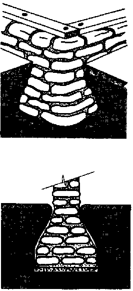
Piles of stone and rock can be used to make strong foundations and walls, especially if used with a cement-based mortar to hold them firmly together.
Stone and rock have several disadvantages, however:
� if not locally abundant, they are expensive to obtain;
� walls made with rock or stone have many uneven surfaces. Filling in the large cavities in order to made inside walls smooth is time consuming and expensive;
� walls of rock/stone must be thicker than cement block walls if they are to be equally strong;
� building to precise measurements is difficult or impossible; builders planning to use rock/stone should plan slightly larger rooms and construction sites to ensure that the finished building will be large enough.
Cement is an adhesive material that "bonds" or glues objects such as rocks or grains of sand together so that they form a strong permanent piece. A useful cement can be made locally from finely ground limestone. But commercial cements also contain silica, alumunum, and iron oxide. These materials ensure that the mixture will contain a variety of grain sizes. The more different grain sizes there are' the stronger the cement will be.
Because of its bonding action, cement is used as an ingredient in many construction materials including:
� mortars
� concrete
- poured
- reinforced
� blocks
- concrete blocks
- sand-cement (sand-crate) blocks
- stabilized earth blocks
Each of these materials is discussed below.
Generally, cement is used two ways:
- as an ingredient in mortars, (pastes used to bond bricks, blocks, or stones, and to plaster walls);
- as an ingredient in concrete.
Mortar is a general term for any mixture of cement with sand and either lime or clay. The ingredients are mixed in varying proportions with water to form a paste that can be used:
- to bond bricks, blocks, or rocks;
- as a wall finish (plaster, stucco).
The tables in Appendix 5 give recommended proportions for different mortar uses.
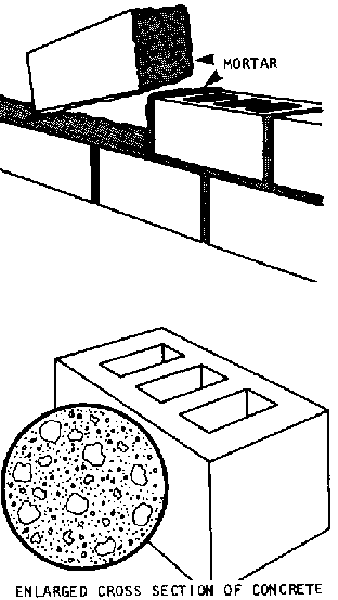
Concrete is a mixture of sand, gravel, and water that is held together and given strength by cement.
The strongest concrete has particles ranging from very fine sand to gravel of 3.75 meters across. Some builders and manufacturers refer to the sand as fine aggregate, and the gravel as coarse aggregate.
Before concrete can be poured, wood forms must be carefully built to hold it in the exact size and shape desired. When the formwork is ready, plain wet concrete is mixed, poured in the forms, and allowed to cure (dry) for a few days to a few weeks (depending on the weather and type of construction!.
Plain poured concrete can be used to build:
� foundation footings (pads of concrete that distribute a building's weight over a wide surface);
� blocks for foundations and walls;
� floors.
The proportions of cement, sand, and gravel vary according to the planned use of the concrete. But these proportions are always referred to in the same way by builders. For example, a formula often used for foundations, 1:2�:3, means concrete composed of 1 part cement, 2� parts sand, and 3 parts gravel. A builder using this formula would need 2� wheelbarrows of sand and 3 wheelbarrows of gravel for every wheelbarrow of cement. In addition, he/she would need approximately 23 liters of water to be added to the mixture.
Reinforced concrete combines two materials with opposite characteristics:
� plain, poured concrete: resists downward pressure (compression), but will not bend; it cracks instead;
� iron rods: will bend (they have tension strength), but they will buckle under compression,
Reinforced concrete is prepared and handled as plain concrete is, except that an iron rod, or a series of rods, is fastened inside the form before the concrete mixture is poured in. (In some cases, bamboo stalks can be used for reinforcement in place of iron rods. See page 188).
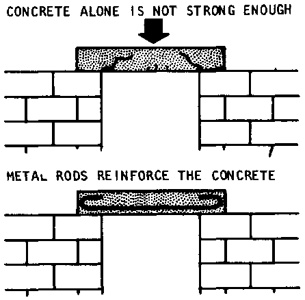
Reinforcing concrete either with iron or bamboo is fairly easy and can multiply the strength of the concrete 2 to 5 times in:
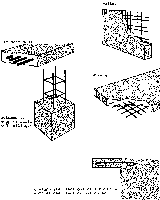
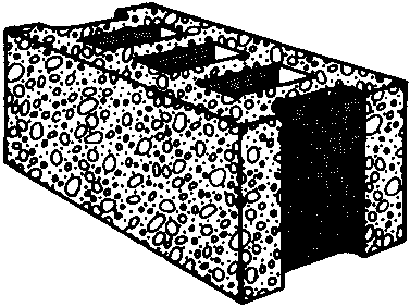
A variety of blocks can be made by combining cement with other ingredients. All these blocks are useful for foundations and walls and can be produced locally if the proper ingredients are available. They can either be made by hand or with a simple press. A press is generally more efficient and produces a stronger, more tightly-packed block than can be made by hand.
Whether made by hand or press, the blocks can be solid or hollow, depending on the mold chosen. Hollow blocks use considerably less material, reduce weight, and improve insulation. They are not as strong as solid blocks. But in sections of a building where additional strength is required, the hollow parts can easily be filled with poured concrete or other reinforcing materials.
TWO BASIC BLOCK-MAKING PROCEDURES
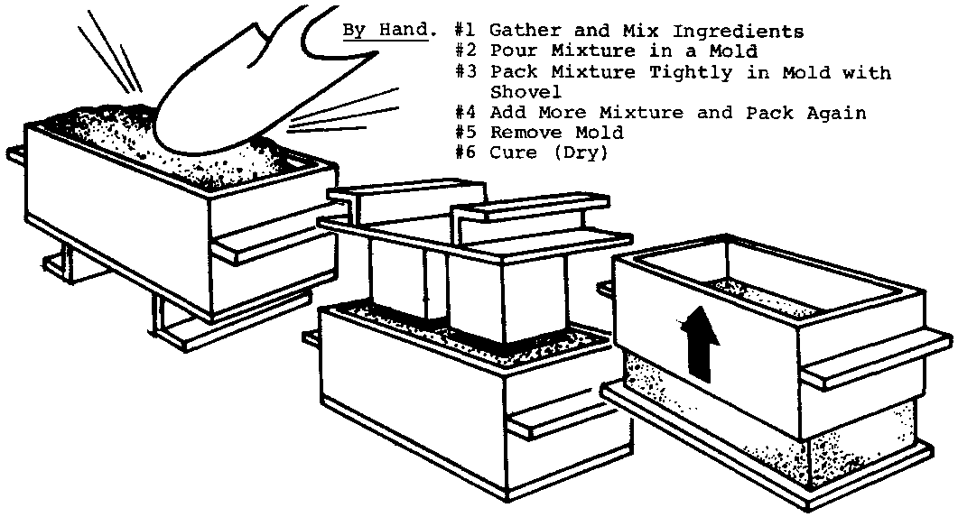
By hand:
#1 Gather and Mix Ingredients
#2 Pour Mixture in a Mold
#3 Pack Mixture Tightly in Mold with Shovel
#4 Add More Mixture and Pack Again
#5 Remove Mold
#6 Cure (Dry)
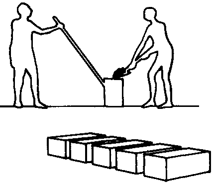
By Hand-press.
#1 Gather and Mix Ingredients
#2 Pour Mixture in a Mold
#3 Pack Mixture Tightly in Mold with Press
#4 Add More and Pack Again
#5 Eject Block from Press
#6 Cure (Dry)
Concrete blocks are excellent for foundations and walls. They are made from a mixture of 1 part cement, 2 parts sand and 4 parts gravel. As manufactured commercially they:
� are usually among the strongest blocks available (in fact, they are stronger than necessary for 1-story buildings);
� have excellent insulating qualities;
� are the most uniform blocks (important for accurate, durable construction).
However, they are by far the most expensive block a community could use.
Concrete blocks can be made locally if limestone (or commercial cement) sand, and gravel are available in large quantities near the site. The process is simple, but timeconsuming. Generally, the blocks must be made about a month before they can be used for construction.
Sand-cement blocks are strong blocks made of 1 part cement to 6-8 parts sand. They cannot be used to support roof loads without some reinforcement, but are more than adequate for 1-story buildings.
Because of the high proportion of sand needed, sand-cement blocks are only practical for construction where there is a lot of sand (sand-cement blocks are not generally made commercially). But if the sand is available, sandcrete block-making is a quick and efficient process. Sandcrete blocks only take 12 days to cure (dry), less than half the time required for concrete blocks.
These are blocks in which clay soil, rather than sand, is mixed with either cement or lime. The amounts of cement and soil needed for a good mixture can only be determined by testing how much the soil shrinks when dried (the procedure is simple and can be followed easily by any community group).
The blocks are formed in the same way as sand-cement blocks and can be used for all the same purposes. They are especially suited for low-cost construction in areas where sand is not available in large-enough quantities for sandcrete. However, great care must be taken to keep organic material out of the clay soil used in the mixture. Otherwise the mixture will not form a strong bond. (This too can be done with a simple test of local soil samples. See page 146).
Stabilized earth blocks can be used after only 8 days of curing.

In surveying locally available materials, it is useful to keep in mind that:
� adobe brick is best for dry, hot areas but needs a rock or concrete foundation and protection against rain;
� rammed earth walls, though made of the same ingredients as adobe brick walls are not as strong or as permanent;
� stone and rock are good but require more heavy, hard work than other construction materials;
� sand-cement blocks are strong and easy to make, but they require cement and a lot of sand;
� stabilized earth blocks are cheaper than sand-cement blocks and about as strong; but care must be taken to see that the right mix of soils is available in the area;
� concrete blocks are good but very expensive if purchased commercially; they can be produced locally but take a month to prepare;
� plain poured concrete is a strong and versatile material especially suited to foundation footings, foundation walls, and floors; it can be made inexpensively in most communities if limestone or commercial cement is available;
� reinforced concrete is the strongest, longest-lasting material of all (especially in wet and stormy climates and earthquake areas). But it is very expensive.
After the size and floor plan of a new building have been decided on along with its site and position; and after a preliminary assessment of the construction materials that may be used has been made, the next crucial step is to develop detailed written plans (or blueprints) to guide each part of the construction. These plans must answer several questions about each part of the building from the ground up:
FOUNDATIONS
� How deep in the ground must the foundation be set?
� How thick must it be?
� How high must it be?
� What will the foundation be made of? Will it be reinforced?
FLOORS
� Will the floor be made of cement or packed earth?
� How much should it be raised above the level of surrounding ground?
� How thick should it be?
WALLS
� What will the walls be made of?
� How thick should they be? Should they be reinforced?
� How will window and door frames be made and exactly where will they be placed in each wall?
ROOFS
� What will the roof be made of?
� Will it be flat, set at an angle, or set at several angles?
Many of these questions are interrelated. For example, the design of the foundation depends in part, on the weight of the walls and roof it must support; and the design of the walls and roof depends, in turn, on the foundation. Thus, in order to plan the construction effectively, the builder must be able to make some basic decisions about either the foundation or the walls and roof before determining all their exact specifications.
When in doubt about a detail of the construction plans, the field worker or community member may want to seek advice from an experienced local contractor. In most cases, however, construction plans can be drawn successfully for simple 1-story buildings by anyone following the suggestions in this manual.
This part of the manual is designed to help the field worker or community member,
� first, to understand key methods/principles of construction and key technical characteristics of basic materials;
� second, to proceed step-by-step to consider how these principles and characteristics should influence their basic design; and
� third, to actually draw his/her own detailed construction plans.
If the walls of a building are built directly on the ground surface, the weight of the building will soon press them into the earth. This causes the building to sag, crack, or leak.
Foundations are strong platforms built below ground level, where they won't sink. A building with a foundation can "stand" securely.
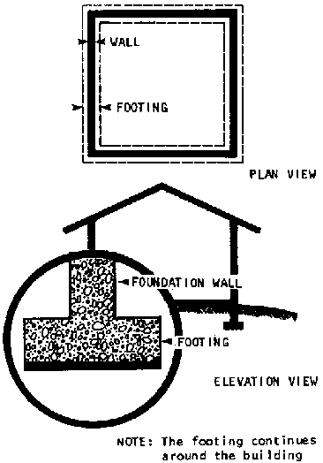
The foundation of a well-constructed building does several things:
� it provides a level platform for the building to stand on;
� it helps protect the building if earth tremors, strong winds or rains shake the structure;
� it keeps out water and dampness.
Here's a list of things the foundation must NOT do;
� sag;
� dissolve (or rot) by water erosion;
� crack from stress at a certain point;
� slip on uneven ground
� buckle under pressure of water in the ground (this is called "scouring");
� collapse from the weight of the building.
Foundations for 1-story structures generally consist of two parts: a footing, and a foundation wall.
The footing should be a pad of concrete resting in a level trench dug under the position of all walls that will support the roof.
The foundation wall is a solid wall attached to the footing and rising to ground level at the point where the ground is highest under the building. The foundation wall can be made of many different materials. Each material must be planned for in a different way.
Note: There are other foundation designs such as pier and beam, or post and beam that communities with access to heavy wood beams might wish to use. See Appendix 7 for reference materials that discuss these designs.
All foundations should have a concrete footing. The concrete can be poured directly into the foundation trench, or into wooden forms in the trench. In either case, the bottom of the trench must be level and the sides of the trench or of the wooden forms must be square: that is, they must be exactly vertical, at 90� to the trench bottom.
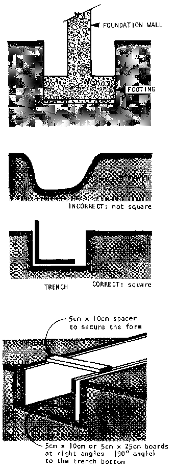
The depth of the trench in which the footing rests depends on:
� what the foundation wall is made of;
� the stability and strength of the soil;
� the frost line (this only applies in areas where temperatures drop below freezing in winter; the frost line is the maximum depth to which soil freezes locally);
� the unevenness and/or slope of the ground.
The width and thickness of the footing depend on what material the foundation wall is made of.
The foundation walls can be made of rock, or they can be made of blocks of concrete, sand-cement, or stabilized earth.
All of these materials are strong enough to support the walls and roof of most 1-story buildings. The choice depends on what materials are available, the builders' budget, and whether or not earthquakes or severe weather conditions will require reinforcement in the foundation.
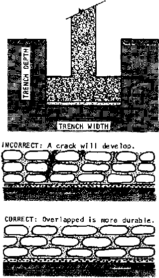
Rock Foundation Walls. A rock foundation wall is built by setting stones that are 20 to 40 cm. long in mortar. The rocks must be cleaned so that no rocks remain on them. All the spaces between the rocks must be filled with mortar (these spaces are called "joints"). In addition, and most important, they must be laid so they overlap. If a straight line can be drawn between the rocks from the top to the bottom of the wall, a crack will develop.
Rock foundations are the least expensive to build. However, they require a large number of rocks, and it is difficult to clean, level, and overlap the rocks properly.
If the building position is on rocky ground, or on dry, well-packed clay soil, the footing for a rock foundation wall should be 4 to 8 cm. thick.
In less stable soils, such as sand, or gravel, the footing should be at least 10 cm. thick. In soft black soil, drained marshland, and made earth, the footing should be reinforced and should be 10 cm. thick.
In rocky or hard-packed clay soil, rock foundation walls need only be 30 cm. deep. In other soils, they should be at least 45 cm. deep.
Rock foundation walls should be at least 30 cm. thick, and they will be much more stable if they are flared at the base to 45 cm.
Block Foundation Walls. Whether built of concrete, sand-cement, or stabilized earth, block foundation walls are made by laying level rows of blocks on concrete footings until the wall reaches the planned height of the floor. Each row of blocks, called a course, is joined by mortar, as are the ends of each block.
Block foundations cost more to build than rock foundation walls (except in areas where the rock must be transported over large distances), but block foundation walls can be put up faster, and they are easier to build well.
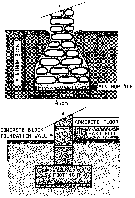
In rock or firm clay soil, a block foundation should be 45 to 60 cm. deep. In less stable soil, a block foundation should NOT be used.
The width and thickness of the footing depend on the size of the blocks being used. In general:
� the footing should be as thick as the blocks are wide;
� the footing should be 3 times as wide as the blocks.
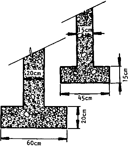
Frost Line. The frost line is the depth to which the ground in any area freezes in the winter. In climates with freezing temperatures, the footing must be entirely below the frost line.
The table below gives suggested depths to be safely below the frost line in different climates:
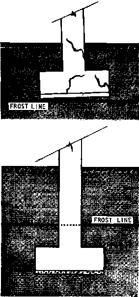
|
Lowest Temperature in Winter, Degrees Celsius |
Safe Minimum Depth for Top of Footing |
|
-1� |
45cm. |
|
-5� |
75cm. |
|
-11� |
90cm. |
|
-18� |
1.05m. |
|
-22� |
1.20m. |
|
-28� |
1.30m. |
Sloping Ground. If a building is built at an angle on a slope, it will tend to slide downhill, causing the foundation and walls to slip and/or crack. Thus if the ground under a building slopes or is uneven, the trenches for the foundation footing must be completely levelled.
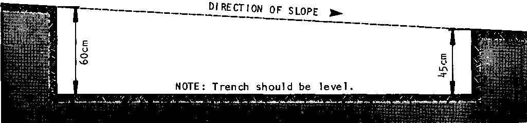
If the ground slopes sharply, it may be easier, or necessary, to "step" the trenches. When block foundation walls are planned, it's important to make each step the height of one or two courses of blocks.
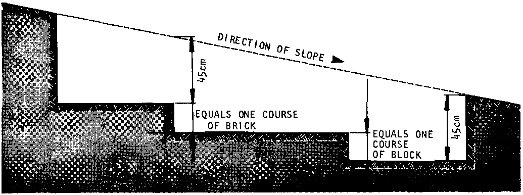
In general, the best way to decide what the foundation walls will be made of is to choose the least expensive and most easily accessible material.
Once the choice has been made between rock and blocks, the depth of the trenches and the dimensions of the footing and foundation wall may be approximately determined by using the figures outlined on pages 85-86.
It is important to remember, however, that these preliminary figures are only approximate guidelines. Any number of local conditions can make a deeper, stronger foundation advisable.
One of the best ways to determine whether preliminary foundation plans are safe is to compare them with the foundation structures of buildings in the local area. The field worker or community member should ask:
� How deep are the foundations of buildings that have cracked walls or other signs of weakness?
� How deep are the foundations of buildings that have lasted well?
� How wide and thick are the foundation footings and walls of weak buildings? Of strong buildings?
� What are the foundations of weak buildings made of? What are the foundations of strong buildings made of?
If preliminary plans for the foundation are similar to those of strong buildings built nearby on the same kind of soil in the local area, they should be safe to use. If the preliminary plans are similar to those of weak buildings they should be strengthened before the start of construction.
After the materials and dimensions of the foundation have been planned, the last step before construction of the foundation can begin is to draw a final foundation plan.
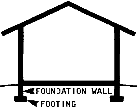
The plan should include two simple drawings:
- a scale drawing of the footing and foundation wall as they would look in a cross-section;
- a scale drawing of the footing and foundation wall measurements as they would look if seen from above.
Both these drawings are simple to produce with a ruler. Step-by-step instructions will be found in Appendix 2.
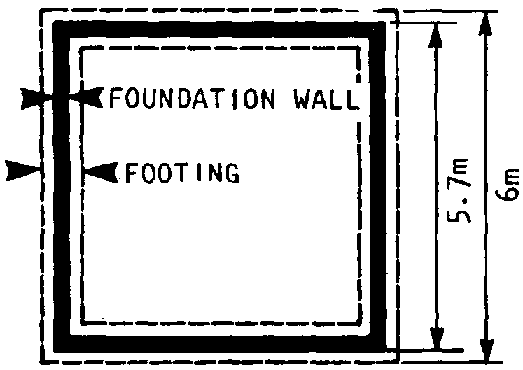
To be comfortable and safe, the floor of a building must be:
� dry;
� level;
� smooth, but not slippery: movement should not be obstructed by holes or bumps, but the surface should not become slippery when wet.
The most important of these is keeping the floor dry.
In many climates, the ground under a building will be damp, even in periods between rainfall.
In areas of heavy rainfall, if the floor is at or close to ground level, water will come in under the doors and damage the floor.
For both these reasons, the floor of all buildings in areas where there is heavy rainfall should be raised at least 20 to 30 cm. above ground level to protect it from moisture.
The best way to do this is with "dry fill." Dry fill is a layer of any material that will not hold water. Typical materials used for dry fill include: small stones, broken bricks, clumps of hard earth, and gravel.
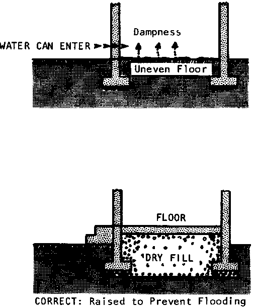
Two basic types of floors will be discussed in this manual:
� hard-packed earth floors,
� concrete.
In areas with large local wood supplies, wood floors are also good.
HARD-PACKED EARTH FLOORS
Hard-packed earth floors are much less expensive than concrete. They are adequate in dry climates, but can be uncomfortable and unhealthy in wet climates or low-lying areas, even when ample dry-fill is used.
Earth floors must be made from hard earth taken from below ground level. Soft topsoil, or any soil containing organic material will not pack well enough. The hard earth should be placed above the dry fill in a tightly-packed layer 10-15 cm. deep.
CONCRETE FLOORS
Concrete floors cost more than hard-packed earth. They are also stronger and much better-suited to wet climates and low-lying areas.
A concrete floor is made simply by pouring a layer of concrete over the dry fill. (Hard laterite is the best kind of fill for a concrete floor.) The best thickness of the concrete layer depends on the planned use of the floor (see table on right).
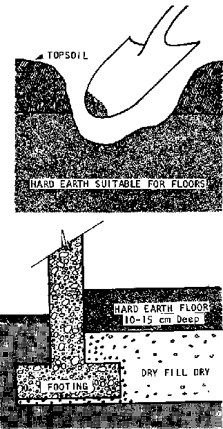
|
Suggested Thicknesses of Concrete Floors |
|
|
Purpose of floor |
Thickness cm. |
|
house, clinic, school |
10 |
|
garage (for vehicles) |
12.5 |
|
farm storage (heavy equipment) |
15 |
In locations where the ground is very unstable or uneven, or in earthquake zones, a concrete floor might need reinforcement for flexibility and additional strength.
Estimating the Amount of Concrete Needed for a Floor.
To determine whether the builder can afford a concrete floor, and to be sure of buying enough materials without buying too much, the field worker or community member(s) should make an estimate of how much concrete will be needed. Step-by-step instructions for the calculations needed will be found in Appendix 3.
A complete, detailed plan for the construction of a building's walls (both exterior and interior) would include descriptions of:
� the material they'll be made of;
� their height;
� their length;
� their thickness
� the exact placement of windows, doors;
� the construction techniques to be used, especially around doors and windows, and where any two walls meet;
� the use of reinforcement (if any) to help the building withstand the stress of very soft ground, high winds, or earthquakes;
� an estimate of the amounts of materials needed for construction.
The basic plan and design of the walls developed earlier should already specify many of these features, especially the materials the outer walls will be made of, their dimensions, and the exact placement of doors and windows.
However, especially when blocks or bricks will be used for the walls, some changes may have to be made before construction can begin. To avoid expensive mistakes or problems during construction, a detailed construction plan of the walls should be prepared.
When the walls will be made of rammed earth, stone, concrete, bamboo, or any other material other than block or bricks, the height and length of the walls should be exactly as planned in the basic wall design.
However, when using blocks of any kind (adobe, sand-cement, cement, etc.) it may not be possible to build a wall exactly the height and length Planned.
For example, if the blocks used will measure 12 cm. high, a wall could be 2.88 meters (24 blocks) high or 3 meters (25 blocks) high; but it couldn't be 2.96 meters high unless one layer of blocks was cut in half, and this is difficult to do. In the same way, if the blocks used will measure 40 cm. long, a wall could be 7.20 meters (18 blocks) long or 7.60 meters (19 blocks) long; but it couldn't be 7.35 meters long unless one block in each layer of the wall were cut 5 cm. short.
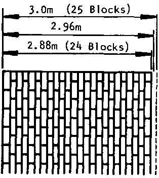
Construction is much easier, and much less expensive if the height and length of block walls are adjusted so that they can be made from a whole number of blocks.
To determine how much the height and length of the walls needs to be adjusted (if at all) simply follow these steps:
STEP 1: D vice the planned height of the wall by the height of one block. If the answer is a whole number, the wall can be built as planned without any adjustment. The result of the division will equal the number of layers (courses) of block needed to reach that height.
Example: The planned height of the walls is 2.88 meters (288 cm.); using 12 cm. high blocks:
288 � 12 = 24 courses of blocks
If the answer is a whole number plus a remainder, compare the remainder with the height of one block and round off to the nearest whole block.
Example: If the planned height of the walls is 290cm. high, using 12 cm. high blocks:
290 � 12 = 24 whole courses + a remainder of 2 cm,
The remainder of 2 cm. is less than 1/2 of 12 cm. (the height of one block), so round the height of the walls down to 24 blocks high.
Example: If the planned height of the walls is 295cm., using 12 cm. high blocks:
295 � 12 = 24 whole courses + a remainder of 7 cm.
The remainder of 7 cm. is more than 1/2 of 12 cm., so round the height of the walls up to 13 blocks high.
STEP 2: The procedure for adjusting the length of a block wall is similar to the procedure outlined above for adjusting the height: divide the planned length of the wall by the length of one block. If the answer is a whole number, with no remainder, the wall can be built as planned without any adjustment. The result of the division will equal the number of blocks needed to reach that length.
Example: If the planned length of the wall is 7.2 meters (720 cm.), using 40 cm. long blocks:
720 � 40 = 18 blocks long
If the answer is a whole number plus a remainder, compare the remainder with the length of one block and round up or down to the nearest whole number of blocks.
The thickness of a wall depends on three things:
� whether the wall is exterior or interior: interior walls usually do not support the weight of the roof and can therefore be thinner; interior walls also play a less important role in insulating the building from heat and cold;
� what the wall is made of: walls made of stronger materials can be thinner than walls made of weaker materials;
� the climate: buildings in desert-like climates need thicker walls, while buildings in tropical climates need thinner walls.
The table below suggests minimum thicknesses for different kinds of walls. The figures given should be adequate for most 1-story buildings (up to 5 m. X 9 m.). However, if there is any doubt about the load-bearing capacity of the walls in a special design, advice from an experienced local contractor should be sought.
|
SUGGESTED WALL THICKNESS FOR DIFFERENT MATERIALS |
||
|
Material |
Exterior Wall |
Interior Wall |
|
Rammed Earth |
37.5-45 cm. |
37.5-45 cm. |
|
Adobe Brick |
30 cm. |
30 cm. |
|
Poured Concrete (not reinforced) |
12.5-20 cm. |
12.5-20 cm. |
|
Poured Concrete (reinforced) |
12.5 cm. |
12.5 cm. |
|
Stone |
30-37.5 cm. |
25 cm. |
|
Block (sand-cement, stabilized earth, cement) |
20 cm. |
10-15 cm. |
As with the height and length of walls, the exact placement and size of windows and doors may have to be adjusted to make construction easier. No adjustments need to be made when the walls will be made of rammed earth, stone, concrete, bamboo, or any other material other than block or brick.
However, when using blocks of any kind (adobe, sand-cement, cement, etc.) the size and placement of windows and doors should be planned so as to make them even with the courses of blocks.
ADJUSTING THE SIZE OF WINDOWS, DOORS
The procedure for adjusting the height and width of the space for windows and doors is exactly the same as the procedure for adjusting the height and length of a wall. Simply think of the windows and doors as though they were walls to be built with blocks. Then, following the procedure described on pages 93-94, increase or decrease the height and length of the windows/doors as necessary.
For example, suppose a window is planned so that it will begin 135 cm. from the bottom of a wall made of 10 cm. high x 20 cm. thick x 40 cm. long blocks. 135 cm. would be 13� layers (courses) of blocks high. So rather than cut a whole layer of blocks to fit the window height, it is much easier either to raise or lower the window 5 cm. so it will start 130 cm. (13 courses) or 140 cm. (14 courses) from the bottom of the wall.
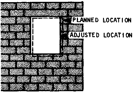
DOOR AND WINDOW FRAMES
The construction plan for walls should show how the door and window frames will be attached to the walls.
Window and door frames are made of wood (5 cm. thick wood is best) to fit the exact size of the wall opening. The frames are permanently attached to the walls, and then the windows and doors are attached to the frames.
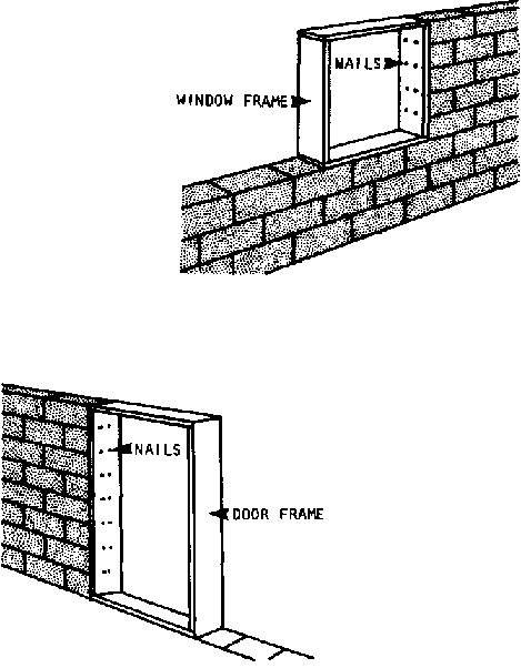
Frames that are nailed right to the masonry or concrete of the wall are the best for preventing drafts and leaks. But they may also be attached to the wall by placing wooden slats in the mortar joints and nailing the frame to the slats.
LINTELS
Lintels are short beams that should always be used to support the wall over an opening for a door or window. Lintels are usually as thick as the wall.
In rammed earth or adobe brick walls, the lintels may be made of 5 cm. thick wood beams. They should extend past the window or door opening about 20% of their length, or a minimum of 20 cm. on each side.
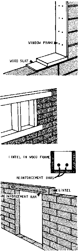
In walls made from any other material, except bamboo, the lintel should be made of reinforced concrete (use two steel bars for reinforcement). Construction will be much easier if the lintels are "precast": that is, made in advance and then placed in the wall like a brick. (For bamboo, see the section on bamboo construction, page 181). In block walls the lintels should overlap the opening � the length of a block on either side of the frame.
INTERIOR WALLS
Interior, or "partition" walls do not support the weight of the roof, as the exterior walls do. Thus they are often thinner than the outer walls, or made of a different material completely. However, they must be attached to the outer walls.
This can be done after the outer walls have been built. But it is usually better and easier to build all the walls at the same time. This is especially true when the walls will be made of blocks or bricks.
The wall construction plan should include a diagram showing how the partition walls will be attached to the outer walls
REINFORCEMENT
In areas where buildings are exposed to stresses such as high winds, severe storms, freezing temperatures, and high humidity, walls should be reinforced. Effective reinforcement will increase the life of any building significantly. Often it enables the builder to construct thinner walls and save money on materials. In earthquake areas, walls MUST be reinforced. (See the section on construction in earthquake zones for special reinforcement techniques not shown here' page 195).
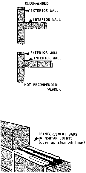
Rammed earth and stone walls are very difficult to reinforce effectively. Block walls can be reinforced in several ways:
� steel rods can be run along the horizontal joints of the wall; the rods should be 1 to 1.25 cm. thick; where they overlap, the overlap should be at least 25 cm.
� barbed wire is an effective reinforcer: it is run, like the steel rods, along the top of each course of brick;
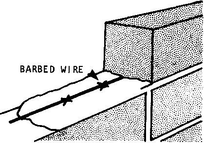
� if hollow blocks are used, the holes in the corner blocks can be used to run steel rods from the foundation up to the roof; then the holes can be filled with concrete:
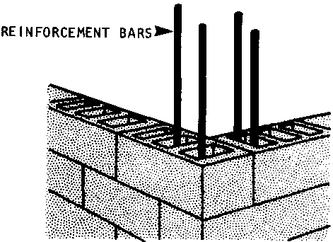
� a "ring beam" can be run around the top of the walls: this is usually a 15 cm. thick band of concrete with 2 steel rods that runs continuously (without seams) around all four walls. Ring beams are mandatory in earthquake areas. (See page 200).
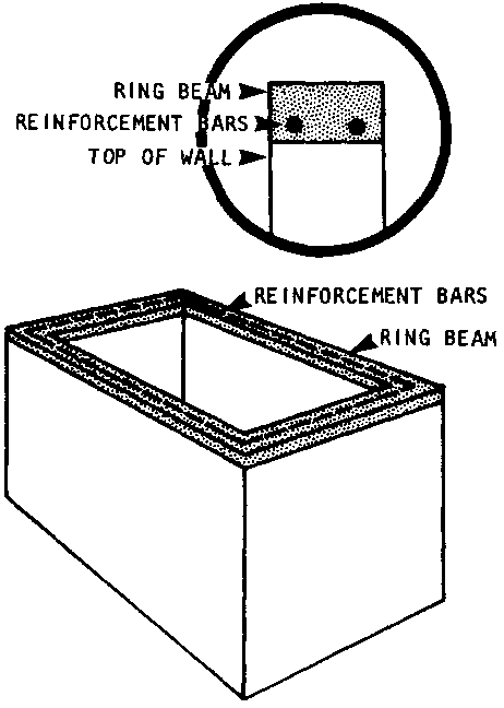
Poured concrete walls are often reinforced; the exact thickness and arrangement of the reinforcement bars should be determined by an experienced local builder, but this is the method most commonly used:
Steel rods ranging from 1-2 cm. are arranged horizontally and vertically, 10-20 cm. apart. They are fastened to each other by lightweight flexible wire and are wired in place temporarily until the concrete is poured.
Concrete that has been reinforced has from 2 to 5 times the strength of unreinforced concrete. This means that, for example, a 10 cm. thick reinforced concrete wall will be as strong as an unreinforced wall twice as thick.
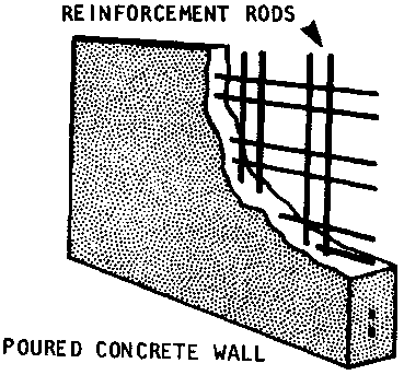
ESTIMATING MATERIALS NEEDED TO BUILD WALLS
Before construction can begin, the builder needs to estimate how much of each of the materials to be used will be needed so that all the supplies can be purchased or assembled in time. Details of the calculations involved will be found in Appendix 4.
When the basic design and construction plans for the foundation, floor, and walls are complete, the field worker and community member(s) should consider what kind of roof the building should have and how it will be constructed.
There are several kinds of roofs. Each can be made of different materials, and each has advantages and disadvantages, depending on the climate, the builders' budget, the availability of materials, and the ease of construction. To make a good decision about the kind of roof to be used, the builder needs to know:
� the basic roof styles; their advantages and disadvantages for the local climate and environment;
� the kinds of materials suitable for each roof style;
� how to design and build each roof style.
All roofs provide protection from the elements: sun, rain, wind, dust, heat, cold, and animals and insects. But each different kind of roof protects against some things better than others. In addition the different roof styles vary in their durability and ease of construction.
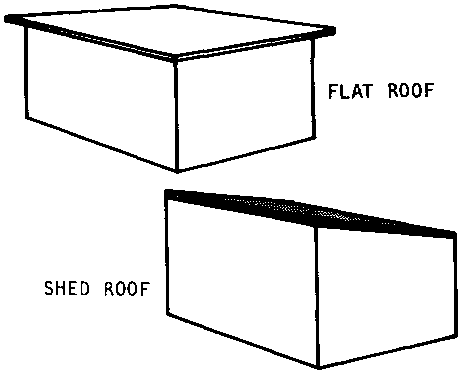
There are four basic roof styles:
� flat: the roof simply lies flat across the top of the building's walls;
� shed: the roof is built at a slight angle, generally from 10-30�.
� gable or double-pitched: the roof forms a triangle over the building. Gable roofs are a combination of two shed roofs, each starting from the opposite sides of the building with the same angle or pitch, hence, "double-pitched";
� hipped: hipped roofs are gable roofs that have been pitched on the ends of the building as well as the sides.
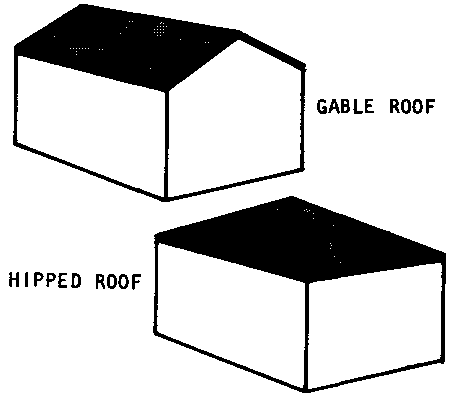
FLAT ROOFS
Flat roofs are generally the most difficult to build and the least suitable of roof styles, especially in buildings wider than 4-5 m.
Here are some of their principal disadvantages:
� because they are flat they tend to sag in the middle unless given very strong support: the most common forms of support, wooden or reinforced concrete beams, must be heavy to be strong; as a result they are difficult to lift into place; reinforced concrete or heavy wood columns may also be used to support flat roofs. However, columns reduce usable space inside the building;
� flat roofs tend to hold snow or rain; this increases the weight on the beams and walls and leads to leaks and warping;
� flat roofs tend to lift in wind and must be securely tied to the building; in areas with severe storms, flat roofs are dangerous.
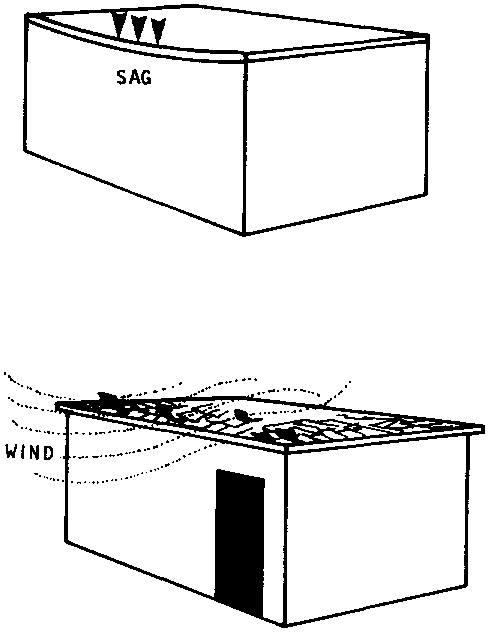
The only advantage of flat roofs is that they can provide extra living space above buildings in dry, desert-like areas.
SHED ROOFS
Shed roofs are generally easier to support than flat roofs. They are usually the least expensive and the easiest style of roof to build.
Because of their pitch (angle), they shed water easily and are particularly good in warm. rainy climates with no snow.
Shed roofs are slightly less subject to wind pressure than flat roofs. However, in stormy areas they must still be very securely tied down to the walls.
GABLE ROOFS
Gable roofs use more materials, require more care in design, and are more expensive than shed roofs.
However, they can be built over large areas (buildings over 10 m. wide) without heavy beam or column support because they are made of relatively light materials and are extremely strong.
Gable roofs are much less affected by wind than flat or shed roofs and are therefore better-suited to areas with strong storms.
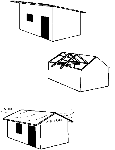
In addition, gable roofs provide excellent insulation against heat and cold. In areas with cold nights or seasons, the triangle formed by the double pitch above the ceiling helps hold the heat in at night. In very hot areas, gable roofs that are ventilated have the opposite effect: they pass heat out of the building quickly, thus helping to keep it cool.
In general, gable roofs are the best, and most adaptable style whenever they are within the builder's budget.
HIPPED ROOFS
Hipped roofs provide more protection against wind on the ends of a building than do gable roofs.
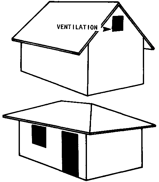
But this is their only advantage over the other roof styles. Hipped roofs are harder to design, harder to construct and use more materials than any other roof style.
Roof materials fall into two categories: those that are used for the frame and support, and those that are used as the roof covering.
WOOD
Wood is the most common material used for roof frames and supports because it is strong and easy to work with. When the covering material will be heavy (tile, for example), wood may be the only practical material for the frame and support of the roof.
One caution: before planning to build a wood frame, or to use wood beams for roof-support, make sure that wood is available in sufficient quantity and size. Wood beams must be at least 5 x 15 cm., and wood used in frame construction should be at least 5 x 10 cm. To estimate the quantities of wood needed for any roof design, see pages 107-114 on roof construction plans.
BAMBOO
Bamboo is an excellent frame material, especially where resistance to wind and earthquake are important concerns. It is light, flexible, and strong.
Where large species of bamboo are available, they can be cut to make tiles for a roof covering.
The chief disadvantages of bamboo are:
� it cannot be easily nailed: most connections are made by tying section together with wire, thongs, or hemp lashings;
� it tends to rot when exposed to dampness or rain.
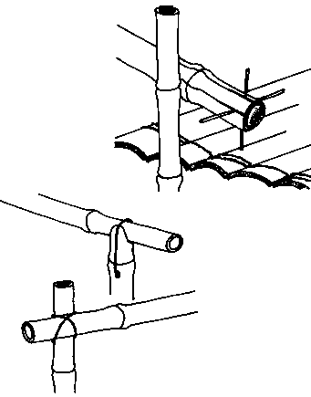
MUD
Mud is the least expensive roof covering, but it has serious disadvantages: it is very heavy; it tends to develop cracks that cause leaks, and it requires very frequent repairs to prevent collapse.
TILE
Tile roof coverings are also very heavy. The materials and labor involved make tile very expensive. Tile roofs should not be used in earthquake zones.
REINFORCED CONCRETE
This kind of roof is seldom needed on small buildings. If it is required, an engineer must be consulted on its design.
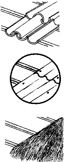
CORRUGATED METAL OR ASBESTOS
Corrugated iron, aluminum, zinc and asbestos sheets have several advantages as roof coverings:
� they are very light;
� they are easy to use on shed or gable roofs;
� they are usually leak-free;
� they are relatively fireproof;
� aluminum sheets are rust-free.
On the other hand, they have some disadvantages, especially on flat roofs:
� they are cold in winter and hot in the summer;
� they rust (except for asbestos and aluminum);
� they are noisy during rain;
� they tend to tear away easily during heavy storms or wind;
� asbestos has been identified as a possible cause of cancer.
THATCH
Thatch is an effective and inexpensive covering for wood or bamboo frames. It is light. In addition, it provides better insulation against heat and it is quieter than metal. However, thatch will not last as long as other roof coverings, especially in wet climates. It is also easily infested by animals and insects unless treated with an effective insecticide.
FLAT ROOFS
Flat roofs are built in three major steps:
STEP 1: Placement of the beams across the width of the building: Wood beams should be about 5cm x 15cm. If bamboo is used beams should be made from the thickest stalks available. For heavy materials such as tile. place the beams at least every 0.6 - 1.0 m. For lighter covering materials, the beams can be slightly further apart if desired. Each beam should be as long as the building is wide plus the length of overhang on both sides of the building.
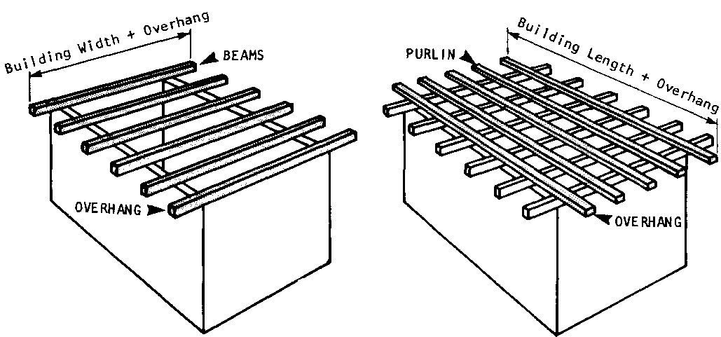
STEP 2: Place purlins across the beams: Purlins are horizontal pieces of a roof frame that support either the roof covering material (in flat and shed roofs), or the pitched rafters (in a gabled or tripped roof). Each purlin should be as long as the building plus the length of overhang on both ends of the building
STEP 3: Cover the roof with the planned covering material, tying, bolting, nailing, or lashing it securely to the purling.
SHED ROOFS
Shed roofs can be built in two ways. Either way, the beams for support can be both thinner and further apart than for flat roofs:
� If one wall going the length of the building is higher than the other, the shed roof can be built with beam supports like flat roofs;
� A much stronger shed roof can be built if the building walls are level. Beams are laid across the walls. Then pitched rafters made of 5 x 10 cm. wood planks are supported at an angle by four struts. Finally, the purlins are attached as in the flat roof and the covering material is tied to the purling:
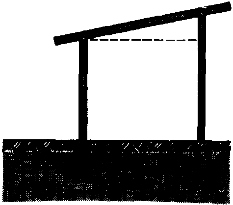
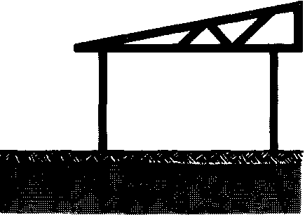
GABLE (DOUBLE-PITCHED) ROOFS
Gable roofs are supported by light weight wood, bamboo, or steel structures called trusses. Basically trusses are triangular shapes strengthened by struts that help distribute the weight of the roof and the force of wind, rain, snow, and earthquake evenly.
The illustrations on this page and the next show how trusses are used and identify their key parts. See the glossary on the next page for definitions of each part.
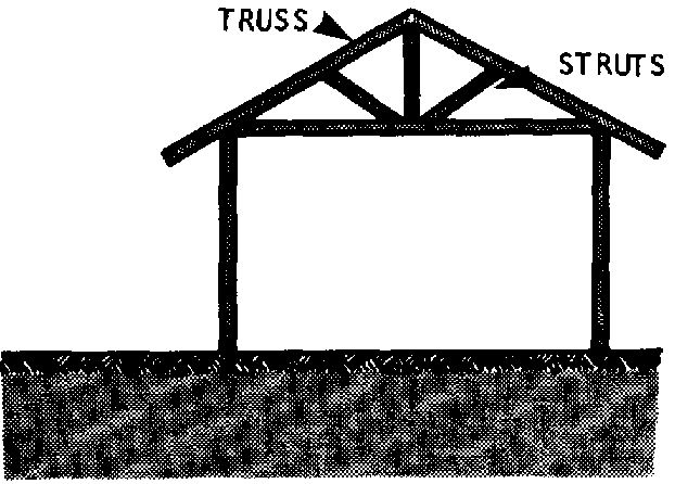
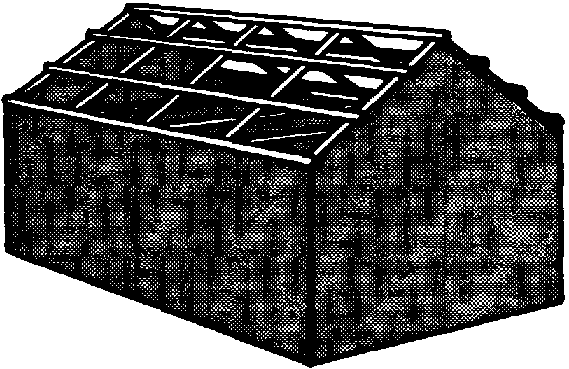
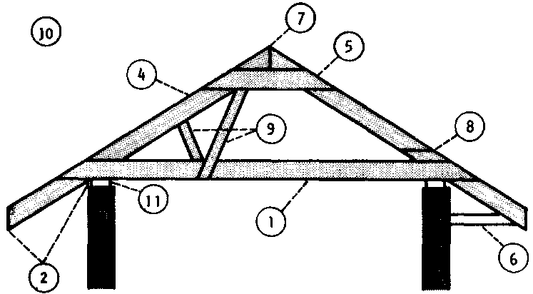
GLOSSARY OF TERMS FOR GABLED ROOFS AND TRUSSES
|
1. Cross |
Tie: Abeam placed horizontally across the width of the building and tied to the walls on each end. The cross tie is the bottom part of a truss-triangle. |
|
2. Eave: |
The part of a roof that overhangs the wall. |
|
3. Purlin: |
Horizontal beams that tie the trusses together. (Not shown) |
|
4. Rafter: |
Either of the angled parts of the truss. |
|
5. Rafter Batten: |
A short beam that joins the top of the rafters in a truss. |
|
6. Rafter Bracket: |
A short beam that supports the rafter when there is a large overhang. |
|
7. Ridge: |
The top point of the truss (also called the apex). |
|
8. Splice: |
A section in a rafter where two long pieces of wood are joined together with nails and a short piece of wood. |
|
9. Strut: |
Any short beam attached to the cross tie and rafters of the truss and used to provide strength. |
|
10. Truss: |
One of several triangular support-structures used to hold up a gabled roof. |
|
11. Wall Plate: |
The part of the wall to which the roof frame is attached. |
Sample Truss Plans
The following pages show the plans for two different trusses for a gabled roof.
The first plan is for roofs on buildings 6 to 9.6 meters wide (20-32 feet in U.S. measurements). The second plan is for buildings up to 6 meters wide (18 feet in U.S. measurements). In either case, the trusses should be placed 2 meters apart.
The charts accompanying each plan indicate the length of each part of the truss for any given building width.
Note: The charts were originally prepared in U.S. measures. Field workers in areas using metric measures should try to find similar charts and plans in their local area, since standard lengths may not be comparable. If metric charts are unavailable, the charts printed here may be used.
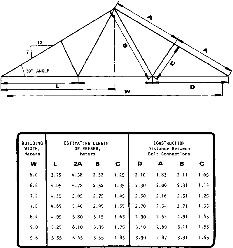
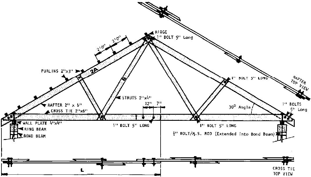
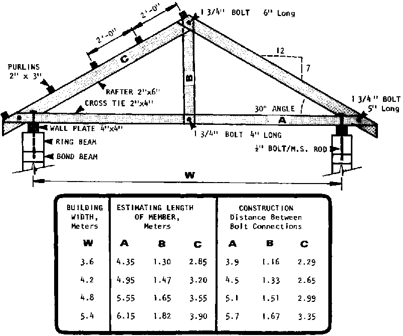
Once the construction plans for the entire building are complete, construction can begin.
This section is designed to help the field worker and community member(s) organize their work to make the construction process flow smoothly, and to provide step-by-step directions for the critical parts of construction that are common to all buildings.
The material is divided into six parts:
� SETTING OUT (LAYING OUT)
� FOUNDATION FOOTINGS
� FOUNDATION WALLS
� FLOORS
� WALLS, WINDOWS, AND DOORS
� ROOFS
In order to begin digging the trenches required for a building's foundation, the builder must first transfer the lines and measurements indicated on his or her foundation plan to the building site. That is, the exact length, width, depth, and position of the foundation trenches must be marked on the ground.
This movement from the plan to the actual site is called setting out. It is probably the most critical step in the entire construction process.
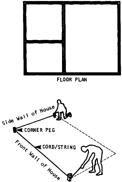
A building that is set out accurately will be:
� level: no part of the floor or foundation higher than another;
� square: walls parallel and the same length;
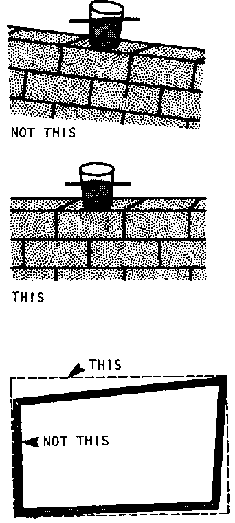
� plumb: straight up and down, not leaning to one side or the other
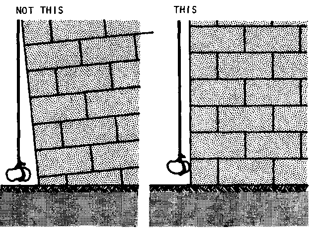
A building that is set out carelessly will be difficult or impossible to construct according to plan. As a result, the finished structure may be expensive to maintain and unhealthful. So it is important to take special care when setting out.
There are three major steps to setting out:
� Orientation of the building on the site;
� Marking a simple outline of the building's foundation on the ground;
� Placing "batter boards" around the foundation outline and marking the position of inside walls, doors, and windows on the boards.
The tools shown on this page are needed to set out a building so that it will be level, square, and accurately measured.
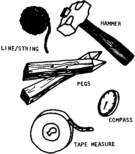
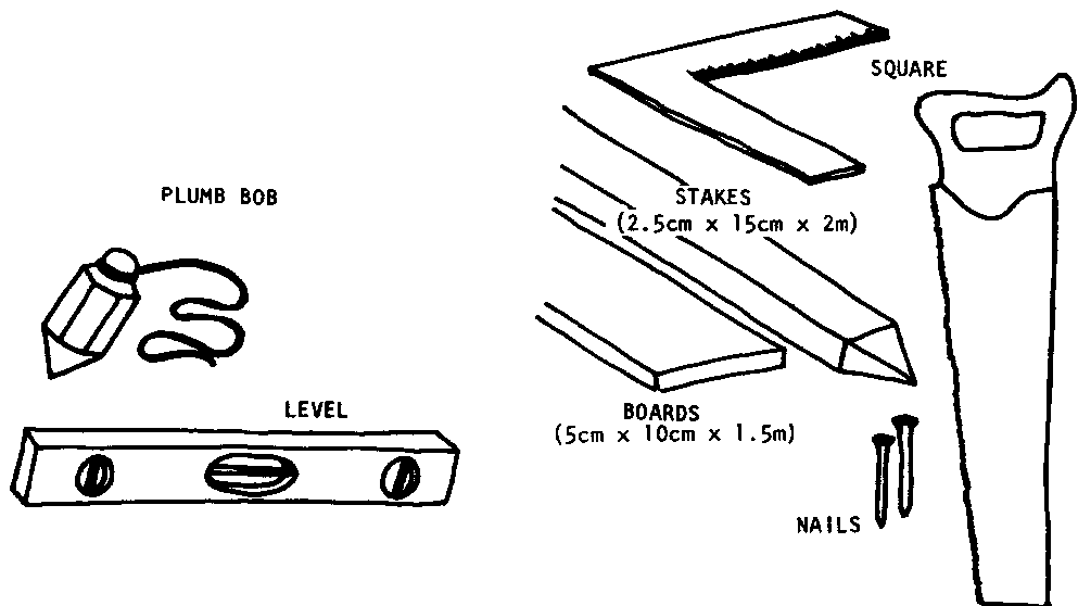
The orientation of a building is the direction its front walls face: north, east, south, west or something in between.
To mark the orientation on the site, first find north. This is easiest with a compass. But if no compass is available, finding north is still fairly simple.
The builder should stand at the building position so that his/her right arm points at the spot where the sun rose in the morning while the left arm points to where the sun set the last night. In this position the builder will be facing north.
Standing in the same position, if the builder moves his/her arms so they form a straight line to the sides, they will be pointing due west (left arm) and east (right arm).
Once the main compass points have been established, use a stick to mark out the shape and position of the building. Add about 2 meters to the dimensions of the building on all sides: the extra space will be needed for supplies and work space during construction.
Next, clear the ground inside this area of trees, shrubs, and loose plant growth. If the topsoil is loose, clear away the top 15cm or so to get down to hard earth: loose soil will not support a building.
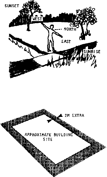
If clearing the land at the position outlined proves too difficult, or if it would require felling trees that are desired for their shade or beauty, consider moving the building a short distance before clearing the land.
The next step is to mark the outline of the foundation on the site using string and pegs.
Three measures are very important:
* the length of each wall must be marked exactly;
* the string must be exactly level;
* the corners must be square: exactly 90�
The length of each wall is easy to set out on level ground. Simply measure it with a tape measure, making sure to pull the measure tight.
When the site is on uneven ground, care must be taken to measure the length of the wall along a level line: following the slope of the ground will throw off the measurements.
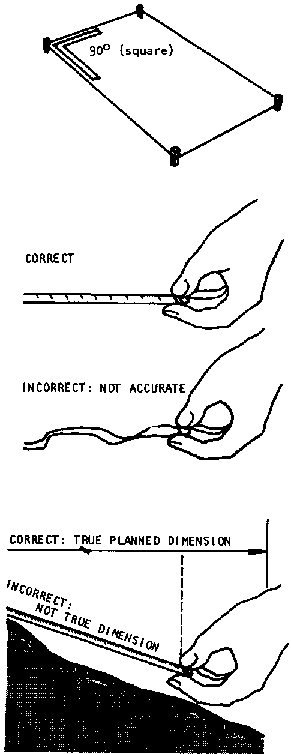
To prevent errors, begin at the highest end of the first wall's length and attach the string to a peg planted at the end-point. Set a new peg every 2 meters to prevent the string from sagging, and test to make sure the string is level by using a plumb bob and mason's square as shown: when the plumb bob stops swinging it will be plumb (straight up and down); the string will be exactly level when it is a 90� to the bob string.
Repeat this process until the length of string set out is equal to the planned length of the first wall.
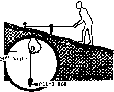
If the ground is sloped very steeply, it may be easier and more accurate to measure the wall's length in steps or stages. To do this run a new length of string from the bottom of every second peg (that is, every 4 meters). Test with a plumb bob to be sure that every peg is straight up and down. In addition, to be sure there are no gaps or overlaps in the measurement of each new stage, plant a small block with a circle on it right next to every other peg: then in measuring the next stage (or step) along the wall, hold the tape measure to the point in the circle that marks the end of the last stage.
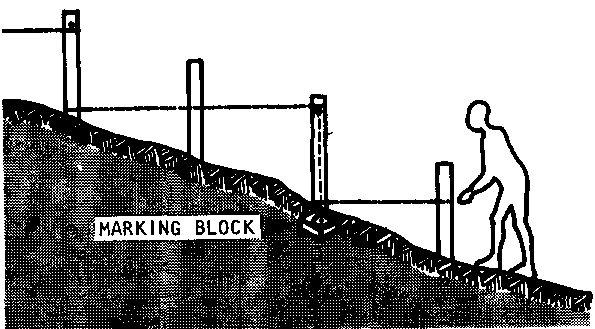
Once the first wall has been set out, the second wall should be set out at right angles to it (90�). There are several ways to make sure that this angle, and the angles between all the walls set out are square:
� A mason's square is good for distances up to 3 meters. Use it to get started, but don't use it to check the entire outline.
� One of the easiest and most accurate methods of checking large distances for squareness is to compare the diagonals. Simply measure the diagonal lines from opposite corners of the foundation. When they are exactly equal in length, all the angles will be 90�. On uneven ground, be sure to use the tape measure along a level line'
� If measuring the diagonals is inconvenient, or if the building is not a simple rectangle, another method is the 3-4-5 calculation:
If the wall on one side of a right angle is 3 units long and the wall on the other side is 4 units long, a line drawn between their ends will always be 5 units long. Here's how to use this rule to test whether the angle between two walls is square: Along the string set out for one wall, measure and mark off 1.5 meters (3 x .5m). Then, along the string set out for the second wall, measure and mark off 2 meters (4 x .5m). Next, measure and cut a piece of string 2.5 meters long (5 x .5m) and hold its ends to the points marked off along each wall. When the 2.5 meter string just touches both marks with no slack left over, the angle between the two wall strings will be exactly square. If the 2.5 meter string is too short or long, adjust either one of the wall strings until it fits exactly.
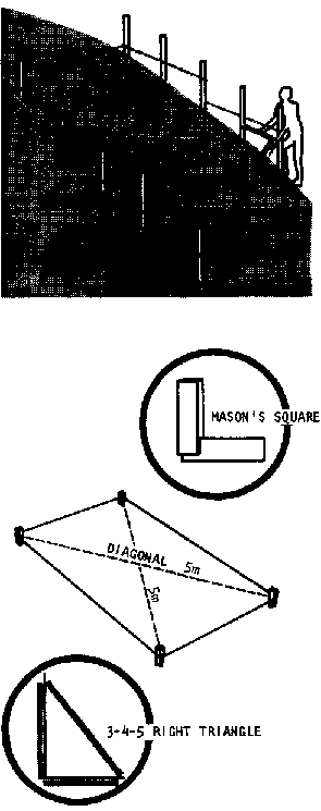
MARKING THE INSIDE FOUNDATION LINES
Once the outside walls of the foundation have been set out with pegs and string, the next step is to set out a second set of lines to mark the inside of the foundation walls. Use the same procedures to keep them level, accurate in length, and square.
The easiest way to begin is to measure the width of the foundation wall and mark it along the strings set out for two opposite walls. Then set out a string between these two points and fasten the ends with pegs. Use a plumb bob to be sure each peg is directly beneath the outside foundation line.
Next, repeat this process for each of the remaining walls. Place a peg at every point where the new lines cross: these are the inside corners of the foundation walls.
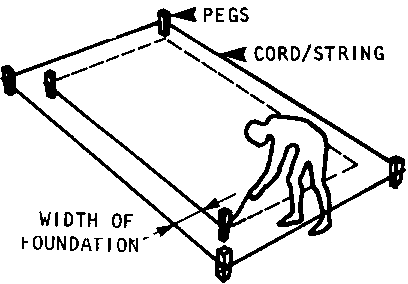
Batter boards are like a single rail fence placed around the building position. They should be placed after the foundation lines have been set out and before any digging for construction begins. Batter boards are essential for two reasons:
� They provide permanent reference points for the position of the foundation walls: these will be needed once the string markings have been removed during construction;
� They can be used to measure and mark off the exact position of doors, windows, and floors, thus making it much easier to build the walls accurately.
To be useful, batter boards must be exactly level and should be set about 1 meter back from the string marking the outside foundation line.
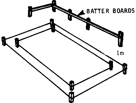
PLACING BATTER BOARDS
To place batter boards around the building postion, first find the highest point on the site about 1 meter outside the outer foundation line and place a wooden stake firmly in the ground.
Nail the first board to this stake so that the top of the board is at least as high as the top of the foundation walls will be. Since the foundation walls must be as high as the floor, this will be at least 20-3Ocm. above the ground.
Next, place a second stake 2 meters from the first and 1 meter outside the outer foundation line. When this stake is secure, nail the other end of the first batter board to it, taking care that the batter board is level. Nail a second board to this same stake and repeat the process of placing new stakes, levelling, and nailing the boards, until the batter boards form a fence that goes completely around the building position.
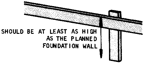
HOW TO LEVEL BATTER BOARDS
A commercially made "spirit level" is the easiest levelling device to use. Place it on the surface - in this case the top edge of the batter board - and keep adjusting the height of the board at the opposite end until the bubble is in the center.
When joining boards at stakes, place the level over the seam of the board to maintain a continuous level line.
An additional check on level can be made at the corners: use an extra board to provide a surface for the level.
Another method is to use a water level: this is a clear plastic hose that is filled with water, Adjust the first end of the hose to a known level mark. When the other end of the hose is placed at the next stake, the water inside will be at the same level as at the first end. To prevent spillage the ends may be plugged until the hose is in position, But all plugs must be removed to get an accurate measurement.
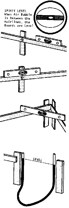
TRANSFERRING MARKS TO BATTER BOARDS
Once the batter boards are complete, all the measurements shown on the written foundation plans should be marked on the boards.
First, transfer the foundation lines marked by the strings set out earlier: run a string from one board to the opposite board directly over each foundation line. Use a plumb bob to make sure this new string is over the corner pegs.
Next, place nails or saw cuts in the tops of the boards where they intersect the strings.
A good system is to use different marks for the foundation lines than those to be used for other important measures such as wall lines and the positions of doors and windows. For example, use small notches cut with a saw to indicate the foundation lines. Then use nails to indicate the wall lines.
Once the foundation lines and wall lines have been marked on the batter boards, the builder is ready to start digging the foundation trenches. Note: the digging will be easier if the strings are left in place until the trenches have been well started.
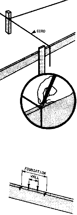
Before the concrete footing can be poured, the builder must dig a trench for it. The depth of the trench depends on characteristics of the site and building that should have been determined in the basic planning stage (see pages 82-88),
However, the width of the trench, and the care with which it must be dug depend on whether the concrete footing will be poured directly in the trench or into wooden forms.
TRENCHES FOR FOOTINGS POURED WITHOUT FORMS
When wooden forms will not be used, the trenches must be dug very carefully:
� the walls of the trench must be plumb (straight up and down);
� the earth forming the trench walls and bottom must be very firm so that there is no danger of the trench crumbling when the concrete is poured;
� the earth must be removed carefully so that the earth at the bottom of the trench is smooth, clear of all trash or debris, and undisturbed (undisturbed means that the earth has not been moved, loosened, or dislodged by the digging);
� the bottom of the trench must be absolutely level: 6-8 measurements with a straight board and level should be made along the length of the trench to be certain of the level;
� the trench must be exactly as wide as the concrete footing;
� the trench must be free of standing water.
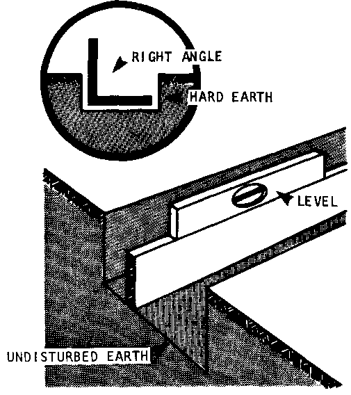
TRENCHES FOR FOOTINGS POURED WITH FORMS
It is much more common to use wooden forms when pouring the concrete footing because the ground at building sites is rarely hard enough to stay in place when the concrete is poured directly in the trench.
Like the trenches for non-form footings, trenches in which forms will be used must be level at the bottom, and hard. The earth at the bottom must also be left smooth, clear of debris, and undisturbed.
However, there is no need to make the side walls of the trench plumb. The only requirement is that the trench be 30-45 centimeters wider than the footing will be, so that there will be room in the trench for the wooden forms and work space for the builders.
A FINAL NOTE ON DIGGING TRENCHES
When digging the trenches, any loose soil, or soil with organic material should be shovelled outside the foundation lines and discarded.
Hard earth that is dug up should be spread evenly inside the foundation lines: it will be very useful as part of the fill under the floor.
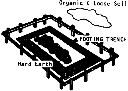
The formwork should be made of boards measuring about 5cm x 15cm or 5cm x 30cm. The boards should be supported by 5cm x 10cm braces called studs. Allow about twice the width of the footing between the studs (but never more than 1.3 - 1,6 meters); the formwork must be strong because concrete weighs 2.5 metric tons per cubic meter.
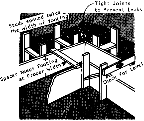
In addition:
� the joints and corners of the formwork must be tight: neither the concrete, nor the water should be able to leak out. If water leaks out it will weaken the mixture;
� the walls of the forms must be exactly plumb (straight up and down), and the tops of the forms must be level: any inaccuracies will weaken the foundation;
� small boards, called spacers, should be nailed to the tops of the formwork to keep the sides of the forms from leaning toward each other before the concrete is poured;
� the formwork should be built so that it may be removed easily without damage: most forms can be re-used;
� if part of the footing will be visible and the builder would like its surface to be smooth, the boards of the formwork must also be smooth: any irregularities in the wood - burrs, bends, chips, and so on - will leave an impression in the concrete.
FORMWORK FOR A STEPPED FOUNDATION
The formwork for a stepped foundation is constructed in the same manner described above. However, if the walls will be made of block or brick, the height of each step of the footing must be equal to the height of the blocks used, or to a whole number multiple of their height. For example, if the blocks used in the foundation are 20cm high,: then the steps must be 20cm or 40cm or 60cm high, and so on.
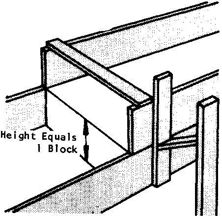
To prepare a strong, durable concrete mixture, the builder must:
� select, prepare, and store the ingredients (cement, sand, gravel) properly;
� use proportions of these ingredients that are suitable for his or her purpose;
� mix the ingredients properly with each other and with water.
SELECTING INGREDIENTS
Cement
The commercial cement most commonly used for 1-story buildings is Portland cement. It is available from most manufacturers. Portland cement, and most locally made limestone cements, can be stored for up to 6 months in a cool, shaded, dry , area. If the cement has hard lumps that are difficult to break or crumble, don't use it.
In humid tropical areas, or areas with heavy rainfall, it may be advisable to purchase "hydrophobic" cement, since this kind of cement can be stored in damp conditions for long periods of time.
Sand
The sand is possibly the most important ingredient in the concrete mix, since it provides most of the plasticity: that is, it makes the mixture easy to work with. There should never be more than 3 parts sand for every 1 part cement. Too little sand in a mixture may result in shrinkage cracks when the concrete dries; too much sand will produce a harsh mortar that will be difficult to work with and may lead to leaks.
Never use sand from the ocean: the grains in ocean sand are too uniform in size and will not make a useful concrete. Any other source of sand is fine. But it is crucial that the sand used be clean.
To test whether sand is clean enough to be used:
� put 5cm of sand in a jar and fill the jar with water:
� hake the jar vigorously for 1 minute and let it stand for 1 hour. The layer of dirt that settles on top of the sand should be less than 6mm thick. If it is more, wash the sand or find other sand (but again, do not use ocean sand).
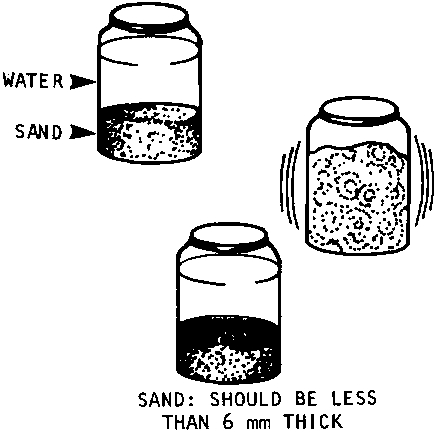
Gravel
Gravel adds strength to concrete because it increases the range of grain sizes in the mixture. Generally it is also the easiest ingredient to find and prepare locally.
Gravel should be clean, and should range in size from 6-18mm.
MIXING THE BEST PROPORTIONS OF INGREDIENTS
The concrete mixture required for a foundation footing may be very different from the mixture needed for concrete used for another purpose.
For example, the average mixture for foundation footings is 1:2 3/4: 4 (that is, 1 part cement, 2 3/4 parts sand, and 4 parts gravel).
But a typical mixture for fence posts is 1:1:1�. The higher proportions of sand and gravel in the footing mixture provide maximum strength and resistance to water. Since fence posts do not need to be as strong or as water resistant as footings, they can be made of a weaker and less expensive mixture.
Table 4 in Appendix 5 recommends average mixtures for different uses of concrete. Following these recommendations will assure builders that their concrete will be well-suited to their needs.
MIXING PROCEDURE
Mixing Area
Concrete should be mixed on a flat surface that will not absorb water. Mix it on a wooden platform about 2 meters by 2 meters. Or, mix it on a cement-sand platform.
Cement-sand platforms must be made a week before concrete can be mixed on them. To build a platform, mix cement and sand on the ground in a 1:6 ratio, cement to sand. Add water, and spread the mixture in a circle about 2 meters in diameter.
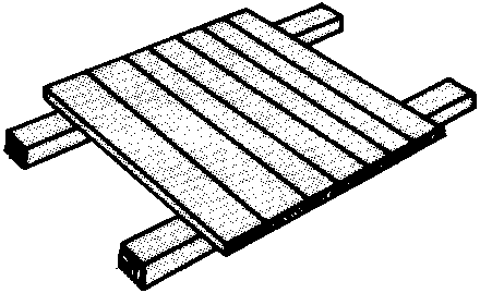
Choosing A Measuring Unit
Since the dry ingredients of concrete, cement, sand, and gravel, are mixed by volume, the easiest way to be sure that the proportions are right is to decide on a standard measuring unit such as a box or wheelbarrow.
Once the unit is chosen, simply fill it to the appropriate level with each ingredient in turn. For example, to make the recommended mix for foundation footings, 1:2 3/4; 4, for each unit of cement, add 2 3/4 units of sand, and 4 units of -travel.
Generally, the easiest measuringunit to use is a gauge box or wheelbarrow that holds 1 bag of cement. The box or wheelbarrow should be approximately 40cm x 40cm x 40cm. Note: to avoid confusion, once the size of the measuring unit has been chosen, do not use different size boxes or wheelbarrows on the site for any purpose.
When using a box:
� the box should have handles on both sides for easy lifting by two people;
� if the materials are close enough to the platform so that they do not have to be carried, it is easier to use a bottomless box: set the box directly on the mixing platform and fill it to measure; then, lift it up to empty the ingredients into the mixture.
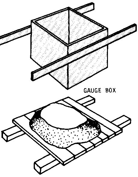
Mixing the Ingredients
The ingredients in concrete should always be mixed in the same order:
FIRST, spread the correct amount of sand on the platform with a shovel.
SECOND, dump the required amount of cement on the sand, and mix the sand and cement until the color of the pile is uniform: there should be no streaks of color.
THIRD, add the required amount of gravel and mix it with the sand and cement until the gravel is thoroughly distributed and there are no streaks of color.
FOURTH, hollow out a hole in the center of the mix. Add water slowly, pushing the ingredients toward the center while turning them over with a shovel.
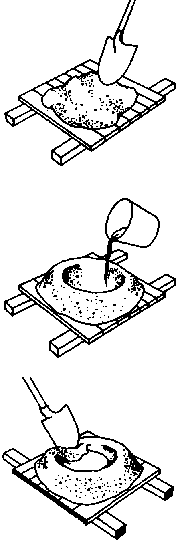
A good test for the correct amount of water is to walk on the mixture:
� if you sink to your ankles or higher, there is too much water;
� if you sink about 5-6cm, you have the right mixture.
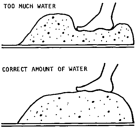
The correct amount of water is important because too much or too little will weaken the mixture:
- if there is too little water, air spaces (weak spots) will form in the concrete;
- if there is too much water, a cement-water paste will rise to the surface, weakening the mixture underneath.
Fresh concrete mix has to be carried to the footing trench in water-tight containers such as wheelbarrows: no water should seep out of the mixture:
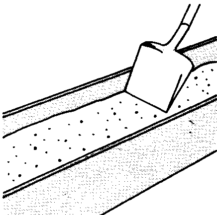
� the mix should be poured within 45 minutes of mixing;
� avoid bumps during transport from the mixing area to the site: vibration will cause the aggregates (sand and gravel) to separate from the mixture;
� it is best to let the mix flow into the trench; do not drop it ; into place or the sand and gravel may begin separating from the mixture;
� once in place, the concrete should be worked up and down with a shovel, rod, or spading tool to break air pockets;
� footings up to 30cm deep can be poured all at once; deeper footings should be poured in layers 15-30cm deep at a time;
� once started, the pouring must be continuous: concrete that has started to set cannot be disturbed;
� if you must stop pouring at the end of a day, place a vertical stop at the end of the poured section;
� when pouring is resumed, roughen the edge of the old section and paint it with a cement-water paste before applying fresh concrete. (Use a stick or any sharp object to roughen the old section).
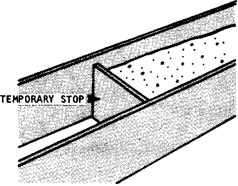
The strength and water-tightness of concrete improve with age. Proper "curing. is important to get the aging process started well.
As concrete hardens, the water in the mix gradually evaporates. ' Prolonging that process increases the strength and water-tightness of concrete.
Immediately after the concrete has set, put a wet covering over it. The covering may be made with wet burlap bags, or a thin layer of wet sand, or wet straw. The covering should be sprinkled with water 2 or 3 times a day for at least 7 days.
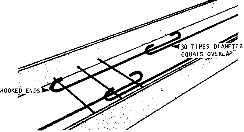
Reinforced concrete footings require the same formwork as unreinforced footings (see page 129). Steel rods are attached to the form before pouring. The rods should be made of steel about 9mm in diameter. They must be clear abd free of rust.
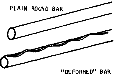
When placing the rods:
� Use steel wire to hold them in place 2.5-5cm above the bottom of the trench, and 5-7.5cm from the sides of the forms. Temporary wood supports may be used while the steel wire is being tied in place, but they must be removed before pouring concrete.
� Plain round bars must be hooked at the ends; deformed bars (bars with curved ridges along their surface) can be left straight since their ridges will hold the concrete firmly.
� The ends of bars should be spliced (overlapped) for a length at least 30 times the diameter of the rods. For example, 9mm rods should overlap for 2.7 meters.
� The rods must be completely surrounded by concrete, and the concrete and steel must be fully and tightly bonded to work properly; any exposed steel will rust through, and this will weaken the steel and destroy the bond.
The recommended concrete mixture for reinforced foundation footings is 1:2�:4.
Footings may also be reinforced with bamboo. See the separate section on Bamboo, page 188.
Once the foundation footing is complete, construction of the foundation walls can begin. The foundation walls may be made of concrete, or any of the blocks made with cement (Sand-Cement, Stabilized Earth). Adobe blocks should never be used for a foundation.
The foundation walls should be built so that the top of the foundation is exactly level with the floor height (at least 1030cm above the ground at the highest point on the building site)
MIXTURE
The best concrete mixture for foundation walls has the same proportions as the concrete for footings: 1:2 3/4 :4.
FORMWORK
The best formwork to use for concrete foundation walls is re-usable unit formwork. Since each "unit" can be used over and over again, the cost of the wood for the formwork can be shared by an entire community.
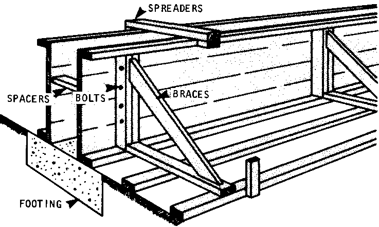
Typical form units are:
� 2.5 meters long;
� either 60cm or 120cm high, depending on the height of the foundation walls;
� made of boards about 2.5cm x 15cm;
� supported by braces about 5cm x 10cm;
� bolted together, not nailed (Bolts make the units much easier to assemble and disassemble. They also make the forms tighter.).
Before concrete is poured, the walls of each unit should be kept apart by 2.5cm x 10cm spreaders. Spreaders can be removed as the concrete is poured, since the concrete weighs enough to keep the forms apart.
After the concrete is poured the walls of the unit should be held together by 5cm x 10cm spacers. Spacers and spreaders should be placed at 1.5 meter intervals.
POURING CONCRETE FOR FOUNDATION WALLS
Concrete for foundation walls should be mixed just as the concrete for footings (see pages 130-135), It should then be poured in layers 15-30 centimeters deep. Pour the first layer for all the walls before going on to the second layer. All the foundation walls should be built up together, rather than one wall at a time.
If possible, it is best to complete all the foundation walls in one day's pouring: this will avoid seams in the concrete.
If it is necessary to stop before completion of the walls, the top surface of the last layer poured should be roughened by scratching it with a stick or placing large pebbles that project out of the surface. This will provide a good "grip" for the fresh concrete when the pouring resumes.
CURING
In warm weather, the forms can be removed after 3 days: in cold weather, leave them on at least a week and preferably 10 days.
As with footings, cover the surfaces of all concrete foundation walls for at least a week with wet sand, straw, or burlap.
Construction of a block foundation wall requires 3 basic steps: . Making the blocks; . Laying the blocks; . Finishing the Mortar.
There are three types of block suitable for foundation walls: concrete blocks, sand-cement blocks, and stabilized earth blocks (not adobe). Each requires different procedures and ingredients.
MAKING CONCRETE BLOCKS
Ingredients
The ingredients required for concrete blocks are cement, sand, and gravel in a 1:2:4 mix. The concrete is mixed using the method described on page 132-136.
Forms
The most common nominal size of concrete blocks is 20cm x 20cm x 40cm.
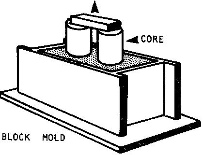
The nominal size of a block is the actual size of the block + the thickness of mortar in which it will be set. Planning for 5mm of mortar between blocks, this means the actual size of the most common concrete block is 19.5cm x 19.5cm x 39.5cm. Thus, the forms used for these blocks should measure 19.5cm x 19.5cm x 39.5cm on the inside.
The forms should be made of wood 2.5cm thick, with removable cores (or dowels) to create holes in the block.
Procedure
The mixture should have enough water to make the mix plastic but not watery. The mix is placed in the form and hand-spaded or vibrated mechanically to remove air pockets.
If the mix is spaded, the forms should not be removed for at least 12 hours (or 2-3 days in cold weather). If the mix is vibrated mechanically, the forms may be removed 30 seconds after vibration.
The cores should be removed first: tap them gently and pull them out slowly. Then slowly remove the outside form. Avoid breaking the corners and edges.
The blocks should be kept damp for 7-10 days and should be sheltered from wind and sun for 28 days before use.
MAKING SAND-CEMENT BLOCKS
Ingredients
The usual mixture of cement-to-sand for sand-cement blocks is 1:6. A mixture of 1:8 can be used for block walls that will not carry roof loads, but this is not sufficient for foundation walls.
The best sand is clean river-bed sand composed of many different size particles. If it is dirty, the sand should be washed, or sifted through a fine screen (4-5mm square), since dirt will weaken the blocks. Do not use ocean sand.
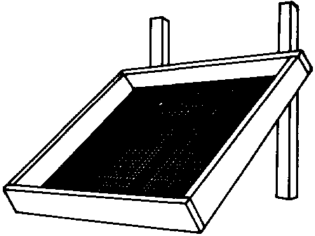
Mixing Site
The site for making sand-cement blocks should be flat and shaded: if the blocks rest on an uneven surface, they will crack before they harden; and direct sun will dry blocks out before they can cure properly. If the mixing site must be in the open sun, the blocks should be moved to a flat, shaded area for curing.
Mixing
Following the mixing procedure for concrete (page 132), measure out the proportion of sand and then mix the cement in thoroughly. Add clean water in the center of the pile and turn the ingredients over at least 3 times until all streaks disappear and the mixture is even. The mix should have the consistency of concrete: wet. but not watery.
Molding Sand-Cement Blocks
Sand-cement blocks may be molded by hand or with a simple hand-press. Blocks made by press are generally stronger and more durable. But blocks made by either method are acceptable.
Hand Molding. If a commercially made mold is not available, a mold' can be made out of 2.5-5cm lumber in the dimensions desired. Typically, these blocks are:
|
Actual SIZE, cm |
Nominal SIZE, |
|
19.5 x 19.5 x 39.5 |
20 x 20 x 40 |
|
14.5 x 19.5 x 29.5 |
15 x 20 x 30 |
|
9.5 x 19.5 x 29.5 |
10 x 20 x 30 |
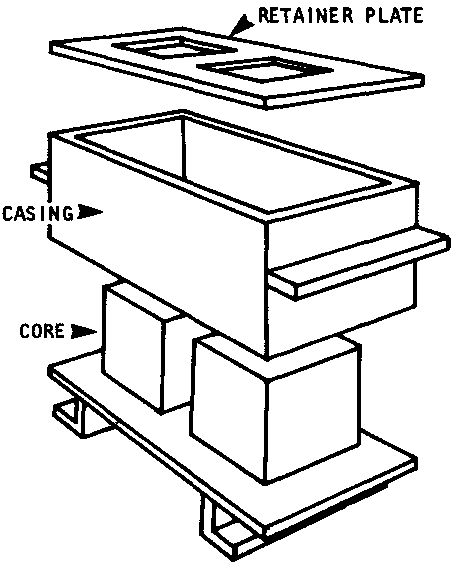
Once the molds of the correct size have been built, shovel the wet mixture into the mold and shake the mold to settle the contents.
Then re-fill the mold slightly over the top and pack the mixture down with a spade or shovel. Scrape any excess off after packing thoroughly.
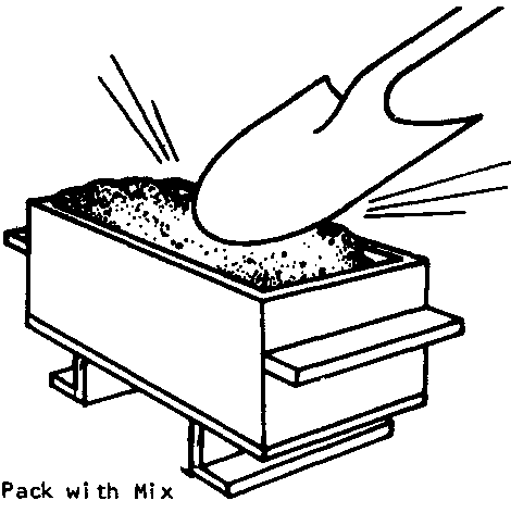
Next, carry the full mold to the curing area.
Turn it upside down gently, and place it a few centimeters away from any previous blocks.
Then, lift the mold off: first the core;
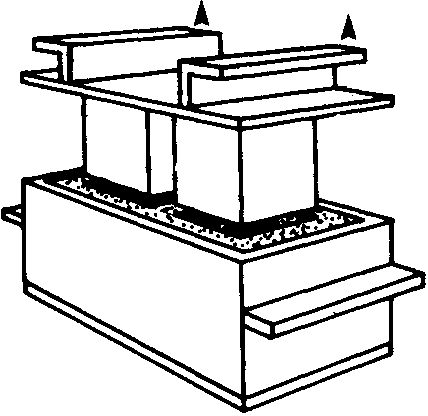
then, the casing. Repeat the process until enough blocks have been made. Using several molds simultaneously will greatly speed the process.
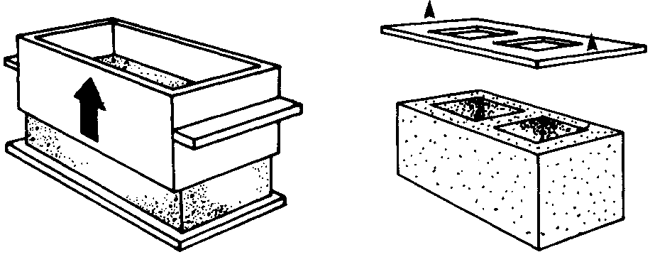
Molding With A Hand Press. There are several types of hand press available for making strong sandcement blocks. Cinva-Ram and TekBlock presses are the most common, but any similar press will work as well.
There are three basic steps in the operation of most hand presses:
� loading the mold box;
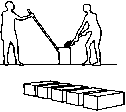
� compressing the mix;
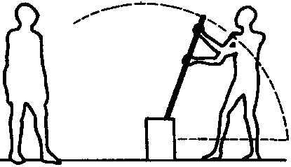
� ejecting the block.
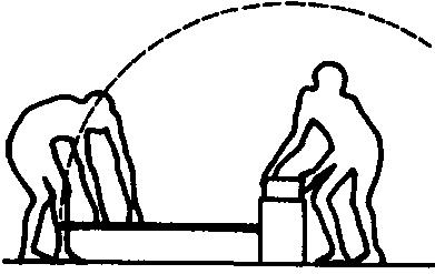
With any hand press, it is a good idea to make a few test blocks before starting production in order to determine the correct amount of mix needed to make a strong block.
Curing Sand-Cement Blocks
Sand-cement blocks should be sprinkled with water after they have set for about 12 hours. They should be dampened at least once a day for 5 days. They should not be laid up in a wall for at least 12 days after being molded.
MAKING STABILIZED EARTH BLOCKS
Ingredients and Soil Selection
The selection of a suitable soil for mixture with cement is crucial in making strong stabilized earth blocks.
There are, roughly, 5 kinds of soil:
� gravel - rock ranging from 5mm to 7.5cm;
� sand - rock particles 5mm and smaller;
� silt - very finely ground rock, spongy when wet, but not sticky;
� clay - very fine grained earth, sticky when wet, hard when dry;
� organic soils - spongy, stringy appearance, odor of decaying, wet wood.
The best natural soil for stabilized earth blocks is sandy clay. As with plain concrete, the strongest blocks have a combination of fine, medium, and coarse particles. Earth that has only one particle size, or has mostly organic and/or coarse particles is unacceptable.
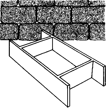
Testing Soil Acceptability
To determine whether local soil can be used to make stabilized earth blocks, use the following test, called the "jar test":
� Fill a glass jar about 1/3 full of soil.
� Add water to the 2/3 mark.
� Shake vigorously for 1 minute.
� Let the jar set for an hour. When the soil has settled there should be 3-4 distinct layers in the jar. If there are not, reject the soil.

Deciding How Much Cement to Mix With the Soil
Once an acceptable soil has been found, you need to determine how much cement to mix with it to make strong stabilized earth blocks. This can be done easily with a "shrinkage test":
� Make a box 4cm deep, 4cm wide, and 60cm long. Grease or oil the insides thoroughly.
� Fill the box with damp, but not muddy, soil.
� Pack the soil with a shovel or spade, especially at the corners.
� Level the surface with a straight edge or ruler.
� Place the box in the sun for 3 days, or in the shade for 7 days, and protect it from rain.
The soil should shrink and develop 3 or 4 cracks. If 6 or more cracks appear, or if the dried soil arches out of the box, reject the soil. It will not make good blocks. As long as there are less than 6 cracks and the soil lies flat in the box, measure the shrinkage by tapping the box and sliding the soil to one end:
|
If the shrinkage is: |
use a cement: soil ratio of: |
|
1 cm or less |
1-15 |
|
1 cm to 2cm |
1-12 |
|
2cm to 4cm |
1-10 |
|
4cm to 5cm |
1- 9 |
|
more than 5cm |
reject the soil, or add sand and repeat the test |
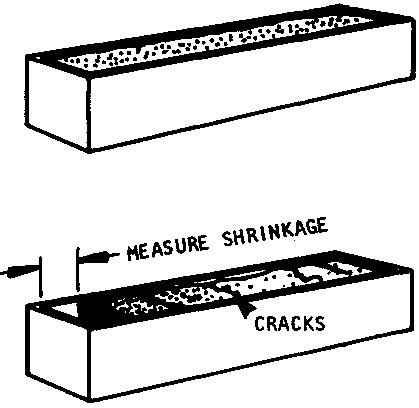
Mixing the Ingredients
Once a suitable soil has been selected, it should be screened through a wire mesh with holes no larger than 5mm.
After the soil has been screened, measure out the proportions of earth, cement, and any sand to be added.
On a platform or other flat area, mix the ingredients thoroughly as for concrete.
Add water slowly with a watering can until the mixture is moist but not muddy.
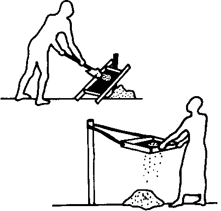
To test whether you have added the correct amount of water, squeeze a handful of the wet mix into a ball:
� If it can be broken in two without crumbling and without leaving moisture in the hand, the amount of water is correct.
� If the mixture crumbles, it is too dry. Add more water and repeat the test.
� If the mixture leaves moisture in your hand, it is too wet. Compress the mixture and allow the excess water to run off. It is best to test the mixture frequently to avoid getting it too wet.

Curing Stabilized Earth Blocks
The moisture in stabilized earth blocks should be eliminated slowly, under cover, with the blocks protected from sun and rain. For the first 3-4 days the blocks should be separated in single rows, never stacked upon each other. They should be sprinkled lightly with water twice a day for this initial period. After 4 days, the blocks may be stacked up to 10 layers high in a pyramid fashion with a little space between each brick. On the 8th day, bricks may be laid up in a wall where they will continue to cure and gain full strength in about 30 days.
When the footing has been poured and has cured for about a-week, and the blocks have been made, construction of the foundation wall can begin. All block foundation walls, whether concrete, sand-cement, or stabilized earth, are laid the same way.
First, stack a number of blocks at intervals along each wall line so that a supply is always at hand.
Next, lay out the planned number of blocks for the first row (course) on or alongside the footing and check to see how well they fit the length of the wall. Very small adjustments in the length of a wall (under 7.5cm over the length of the whole wall) may be made by increasing the size of mortar joints between every 5th or 6th block. For example, if 8 joints are made 1cm instead of �cm the wall length will be increased 4cm without cutting any blocks.
To give the wall strength, the courses (rows of blocks) must be staggered so that the bond between any two blocks rests over the middle of the block beneath them.
To stagger the courses, turn one corner block on the first course so its "head" faces out. Then, on the next course, turn the block at the opposite corner head out. Continue alternating between courses in this way.
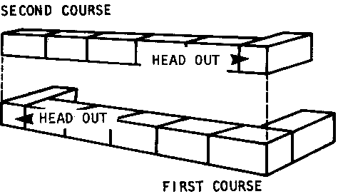
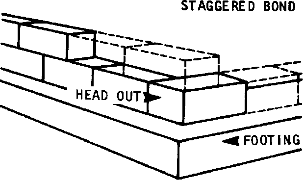
To ensure that the blocks are laid in a straight line, run a string from corner to corner along each wall. For outside walls, attach the string to the batter boards; for inside walls, attach it to a nail hammered between two courses of blocks.
If the string sags, as it is likely to do over a distance, support it with a piece of paper that is weighted with a small rock.
Use the string as a guide, laying each block up to but not touching the line. The string can be moved up later for each new course of blocks.
Once the string is in place for the first course, you are ready to prepare the mortar.
The recommended mix for mortar to lay blocks is 1:3, 1 part cement to 3 parts sand. Mix these ingredients with each other and with water as concrete is mixed (see page 132).
During the dry season, it helps to sprinkle the blocks with water before they are laid in mortar. This prevents them from absorbing too much water from the mortar.
To lay the first course of blocks, use a trowel to spread out a full bed of mortar about 1.25cm thick on the footing. To prevent the mortar from drying out before blocks are laid in it, spread only enough for 4 or 5 blocks at a time.
Using the batter board lines as guides, position the first block the corner block - very carefully: an error here will cause problems that are hard to correct.
When the corner block is positioned, tap it down firmly - do not pound until it is solidly bedded in the mortar.
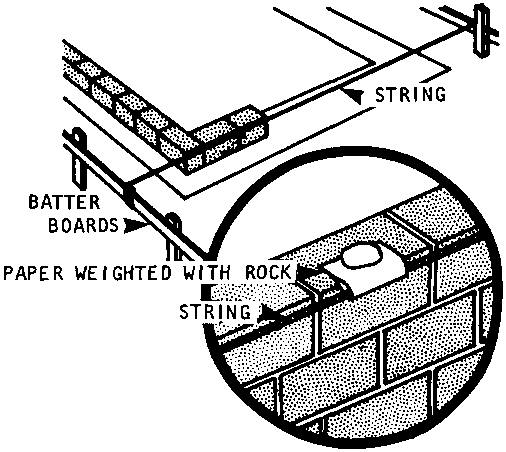
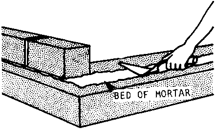
Butter the ends of each new block to bond the vertical joints between blocks. Press each new block against the previous one until a solid mortar joint about 15cm wide is formed.
Keep trowelling of the bed to a minimum: it will draw water out of the mortar mix, weakening the bonds.
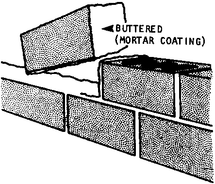
Any excess mortar that squeezes out between blocks should be scraped off. It can be re-used if it has not dried out. Once mortar dries out it must be discarded.
After every 3 or 4 blocks are laid, check the course with a level. If it is not level, remove the blocks, add mortar, and lay them again.
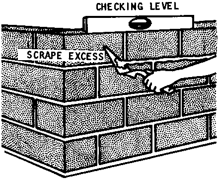
Once the entire first course of blocks is down, build up the corners at least 4 or 5 courses up, or all the way to the top. This will give you something to attach the guide string to for the upper courses.
Use a story pole to check the height of each course, and to check that all corners are going up evenly.
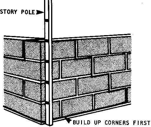
After the mortar has set, but before it has begun to harden, use a bent round bar called a "jointer" to "tool" each joint: run the bar along each horizontal joint, pressing against the mortar firmly. This action will seal the joints, help weatherproof the mortar, and improve the appearance of the foundation wall.
Cure the mortar by sprinkling the wall with water or brushing water on with a broom once a day for 2 or 3 days.
Rock footings and foundations consist of two parts: a concrete base 5-7.5cm thick, and a rock-and-mortar wall. The procedure for laying both the base and the wall is nearly the same as the procedure for concrete footings and block walls.
FIRST, dig the trenches. The bottom 7.5-10 centimeters of the trench will serve as the formwork for the concrete base, so the sides and bottom of the trench should be clear and level. As with any concrete footing, care should be taken not to disturb the earth on the bottom of the trench.
SECOND, gather the rocks. This can be done while the trenches are being dug. The rocks should be 20-40cm long on average. Larger rocks tend to be better because they will use up less mortar. The rocks must be clean, so use water and/or a stiff brush to remove all crusted dirt from their surfaces.
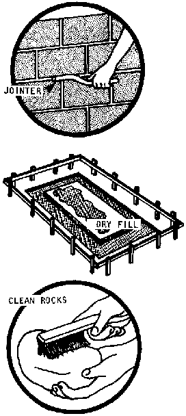
THIRD, pour the concrete. Use the procedure for pouring concrete footings without forms as a guide for this step (pages 127 and 135). Use a concrete mix of 1:2 3/4 :4. Let the concrete cure for 2 to 3 days.
FOURTH, lay the rocks. Tie a string to the batter boards as a guide for laying the rocks. Use a mortar mix of 1 part cement to 3 parts sand. Spread a mortar bed about 1.25-2.0cm thick on top of the concrete base. Position the rocks and tap them into place as if they were blocks.
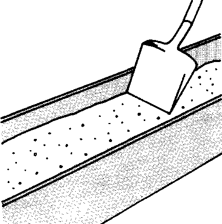
Mortar all the joints between the rocks; the outside surfaces of the walls don't have to be flush, but the joints should be compact.
� Be certain to lap all the joints (that is, stagger the rocks) to prevent a straight-line crack from developing.
� If possible, alternate the direction of the "corner" rocks.
� Finish the exterior mortar joints in the wall with a jointer to strengthen the joints and help waterproof the mortar.
� Keep the top surface of the rock foundation wall as level as possible.
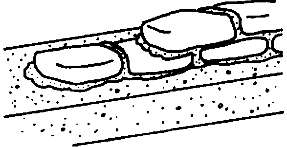
After the foundation walls are complete, but before starting the regular walls, a floor should be started, level with the top of the foundation walls.
Earth floors are easy to build. For drainage, simply place a layer of dry fill inside the area bounded by the foundation. The fill can be made of any material that will not hold water, such as gravel, rock, broken brick, or rubble. The top of the dry fill layer should be about 5cm below the top of the foundation walls.
The fill will be packed down as people walk over it during the rest of the construction process.
When the walls are complete, add a 10-15cm deep layer of hard earth and pack it down either with a shovel, or by walking on it. When the hard earth is well-packed, wet it down slightly, and sweep it out to complete the floor.
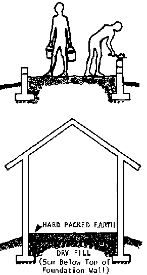
FILL
Like earth floors, concrete floors need a level of dry fill underneath for protection against ground moisture. Dump the fill inside the foundation walls so that it will be packed down by rain and people walking over it during construction of the walls. The fill should be composed of two layers: a bottom layer of dry fill: rock, gravel, broken brick, or rubble; and a top layer of hard earth. If dampness in the area is excessive, a 5-7 cm. layer of sand with a sheet of plastic (or other waterproof material on top) should be laid between the dry fill and hard earth.
The top of the hard earth should be about 1P cm. below the top of the foundation walls.
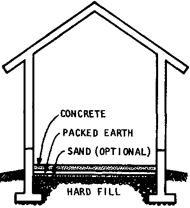
PREPARING TO POUR THE CONCRETE
Concrete floors can be poured at two stages in the construction process:
� after the foundation walls are complete, but before the walls are put up;
� after the walls have been put up.
There is an advantage to the second alternative: since the floor and walls will very likely settle at different rates, the floor may develop cracks if it is connected to the walls. Another advantage is that the walls and doors provide easy protection for the floor while it is curing.
If the fill has been in place some time, check that the hard earth is at the correct level--about 10 cm. below the top of the foundation walls. If it has settled, add more hard earth and pack it down hard. Wet it and then pound it with the end of a steel rod.
Use a straight edge and a level to check that the surface is reasonably level before the concrete is poured.
Pound 6 or 8 wood stakes (about 5 x 10 cm.) into the fill so that their tops will be even with the level of the finished floor (the same as the top of the foundation walls). These stakes will guide you during the pouring, but they must be removed before the concrete settles.
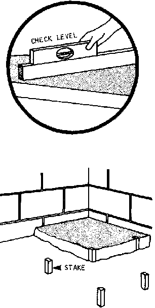
POURING THE CONCRETE
The best concrete mixture for floors is a 1:2�:3 mixture (1 part cement: 2� parts send: 3 parts gravel). Mix the cement as described on pages 132-135.
Then, begin pouring in the corner farthest from where you will finish and work back toward a door so you can get out without walking on the fresh concrete. Pour the concrete at the full thickness-10 cm - don't layer it.
As the area covered grows, begin to level the concrete off with a "screed"--a board about 5 x 10 cm and several feet long that is swept across the surface to keep the mix even with the tops of the guide-stakes.,
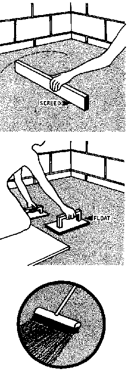
Then, before the concrete sets:
1. remove the guide-stakes and fill their holes with concrete,
2. tap any pieces of gravel and rock that stick out above the surface into the, concrete and smooth the surface over.
Using thin boards to kneel on or walk across the surface without marring the fresh concrete, "finish" the floor by sweeping a trowel or wooden "float" across the surface. A rectangular float is best--approximately 15 x 25 cm. The sweeping action will bring a smooth cement-water paste to the surface of the floor. Be careful not to bring up too much water: if water collects in small pools, the surface of the concrete will be too weak when dry.
After the floor has started to harden, but while it is still workable, sweep the surface with a broom. This will give a rough texture to the finished floor and create a safe, non-slip, surface.
When the floor is finished and is left to cure, close the doors and windows to keep children and animals from walking on the surface.
The floor should cure for at least 4 days, and preferably 10. Keep the surface moist by sprinkling frequently Since so much area is exposed, the concrete can easily dry out too quickly.
Once the foundation walls are complete, construction of the walls, windows, and doors can begin. This part of the manual covers two kinds of wall construction:
- Block or Brick Walls, and
- Rammed Earth Walls.
BLOCKS WITH CEMENT CONTENT
The procedure for making concrete, sand-cement, and stabilized earth blocks is discussed earlier on pages 140-148. For walls made of these materials, build a mold for blocks � the length of a full-size block: the I-length blocks will make the framing of windows and doors considerably easier (see below).
ADOBE BRICKS
Adobe bricks are made from clay and sand. Where available, silt (very fine particle material) will increase the range of particle sizes and strengthen the mixture.
The proportions of these materials can vary considerably. But a good mixture to begin with would include:
� 6 parts sand,
� 2� parts clay,
� 1� parts silt.
Adding straw or chopped grass will always strengthen the bricks.
Make some test bricks and then adjust the proportions as necessary. Some things to keep in mind while experimenting with different proportions:
- silt should never be more than 15% of the mixture;
- A healthy amount of sand is necessary to keep the clay from shrinking. On the other hand, too much sand makes the mixture watery and weakens the bricks as they dry.
Mixing Materials.
Use a mixing platform as for mortar or concrete (page 132) Measure out and mix the proportions and add water slowly: if the mud is too wet it will slump gradually while it dries outside the mold. No large stones or lumps can be left in the mixture, but stones up to 1.5 cm are all right.
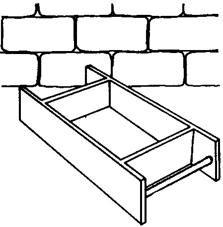
Molds.
The most common adobe brick has a nominal size of 10 x 15 x 30 cm. It is made with a bottomless mold with actual inside dimensions of 9 x14 x29 cm.
Use hard wood for the mold. It may be easier, after some experience, to line the mold with a strip of sheet metal. Molds for several bricks at a time are easy to make and increase the efficiency of brick production.
Like blocks with cement content, adobe bricks cannot be broken neatly into halves or quarters. So, for framing windows and door jambs, it's best to make a halflength mold as well as several regular molds (see window framing below, page 162)
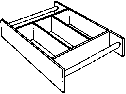
Molding Adobe Bricks.
Bricks can be made on flat, level ground, but using a table is often faster and easier.
Place a clean mold (dipped in water) near the edge of the table.
Fill it with mud, being sure to pack the corners. The mud, like mortar, should be workable but not sloppy.
Clear any excess mud off the mold, but don't make the surface too smooth--the brick will adhere to the mortar better if it has a rough contour.
Slide the mold briskly off the edge of the table and carry it in a vertical position to the drying site.
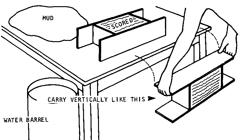
Gently place the mold on flat ground, close to the last brick made. Let it sit for a few moments, then lift the mold up slowly.
Rinse the mold off thoroughly (in a barrel of water) before making another brick with it.
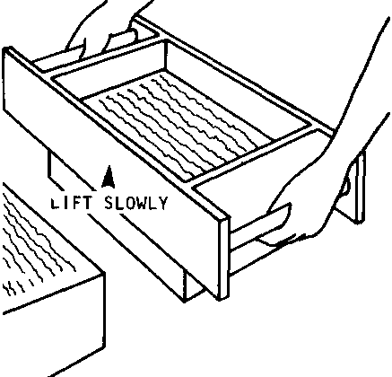
Curing
Bricks must be dry before they can be used; if they dry in the wall they will shrink and ruin the mortar bonds. The bricks should dry in the sun for about 30 days. For the first week or so, the bricks should be protected from rain. Sheet metal provides a good protective cover. After the first week they can be safely exposed to light rainfall.
Turn each brick over every 5 or 6 days to assure even drying.
A Note on Mortar
Adobe bricks are generally laid with mortar made from the some mix as the bricks.
The basic laying procedure for block and brick walls is the same for all types of block and brick and is identical to the procedure for block foundation walls (see pages 148-151),
� The top surface of the foundation, or of the previous course, should be covered with a bed of mortar. Apply the mortar only on the edges of hollow bricks. Cover the entire surface of solid blocks.
� Butter each new block or brick on its ends either before or after it is placed. Again, butter only the edges of hollow blocks; butter the entire head of solid blocks.
� Use string to guide the placement of each new block or brick in a straight line. Position the blocks or bricks up to but not touching the string. Press and tape each one firmly into place so that the mortar joint is 11.25cm thick. Do not pound the block in place.
� After every 2-3 blocks or bricks check the course for level and plumb. Remove and re-mortar any blocks that are out of line.
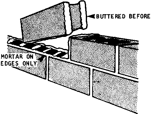
BOND ARRANGEMENTS FOR BLOCK AND BRICK WALLS
There are important differences between the bonds that should be used with blocks and the bonds for adobe bricks.
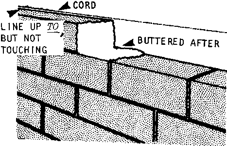
Bonds for BLOCKS With Cement Content
The main bond for blocks with cement content is the staggered arrangement used in block foundation walls. This simple bond is easily continued through corners by alternating the direction of each corner block ( see page 148 for details).
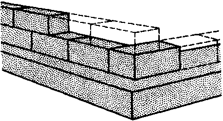
When working with blocks, the intersection of exterior and interior walls is treated much like a corner.
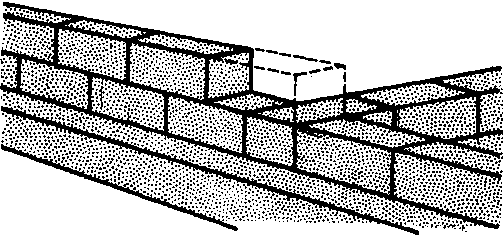
When framing windows and doors, the blocks next to the opening must be half-size in every other course: hence the great advantage of using a half-size mold.
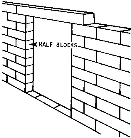
Bonds for Bricks
In any given course, adobe bricks can be laid so that they are stretchers (that is, placed end-to-end), or headers (placed side-to-side).
The corners of brick walls should be built up just as they are for block walls, using stretchers and alternating the direction of corner bricks.
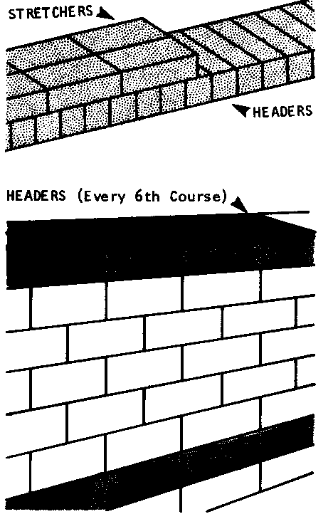
But after the corners are built up, different bonds may be used for the length of the walls. The bonds used most frequently are:
� for bricks with a cement content, headers for the first course and then every 6th course, with stretchers in between;
� for adobe bricks, headers for the first course and then every 4th course, with stretchers in between.
Headers should never come closer than 60cm to corners. Walls shorter than 2 meters (for example porch walls and half walls) should not have headers at all. When beginning a course of headers, start with a � brick: otherwise the bonds over the rest of the wall will not be properly staggered.
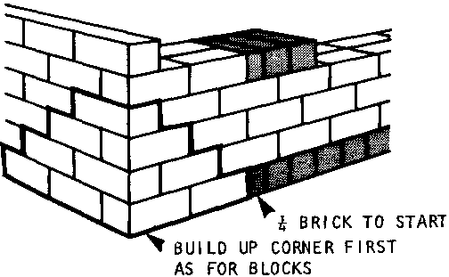
Double Brick Walls
Bricks used in exterior walls may have to be doubled to provide adequate thickness. Double brick walls are laid with alternate courses of headers and stretchers, beginning with stretchers. The illustrations below show how to handle (a) the length of the walls, (b) corners, and (c) the intersection of exterior and interior walls.
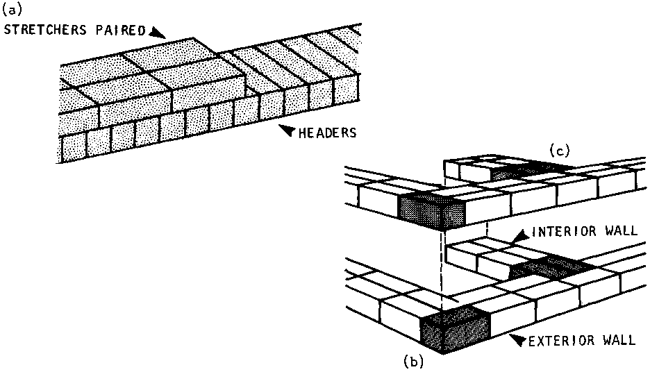
Windows and doors in block and brick walls must be planned so their heights are coordinated with the size of the block or brick used (see pages 95-96),
All windows and doors consist of 3 basic parts: the head, the sill, and the jamb. In addition, there must be a lintel above the opening to support the blocks or bricks over the open space.
FRAMING WINDOWS AND DOORS IN BLOCK WALLS
In block walls, the lintels should be made of reinforced concrete. There should also be a concrete sir-1 about 7cm thick under
the wood sill of the frame.
Frames (heads, jambs, and sills) should be wood, usually 2.5cm x 15cm hardwood lumber in block walls.
To build the space for a window or door in a block wall, follow these steps:
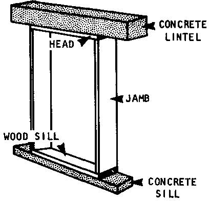
Lintel
1. Make a mold for the reinforced concrete lintel. The mold should be as wide as the wall, as deep as the height of 1 block, and 1� times as long as the window or door is wide.
2. Fix 2 reinforcement rods in the mold and pour a 1:2:4 concrete mixture. Remove the mold and cure the lintel as you would a concrete footing (see page 136).
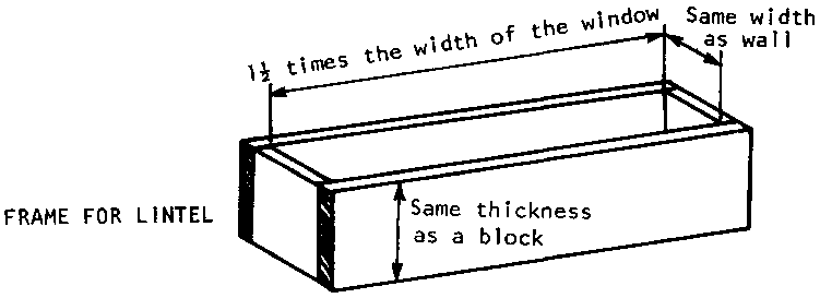
The Sill
3. Make a mold for the concrete sill. The mold should be as wide as the wall, about 7cm deep, and as long as the window or door is wide. Then, pour a 1:2:4 concrete mixture and cure it just as the lintel was cured.
4. Prepare the surface of the wall where the sill will be placed by spreading a bed of mortar on the blocks.
5. Put the sill in place and press it down firmly until the mortar joint is the same thickness as the joints between courses.
6. Immediately check for level and adjust, if necessary, by forcing one end down. If the sill is not level after this, take it off add mortar. and repeat.
The Frame (2.5cm x 15cm hardwood)
7. Place the wooden frame on the concrete sill and hold it in position with temporary braces.
8. Continue laying blocks on either side of the window: the wall must go up evenly on both sides or it will go out of plumb.
9. Attach the frame to the wall with mortar and with nails hammered into the masonry.
10. At the top of the opening, lay the pre-cast lintel like a block:
� if the walls are more than 75cm thick, allow a few hours for the courses below to harden before placing the lintel;
� apply mortar to the blocks or bricks at both ends of the lintel and adjust for the same joint thickness;
� check for level and adjust.
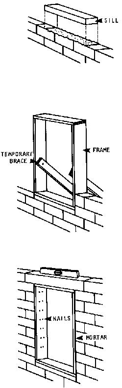
FRAMING WINDOWS AND DOORS IN ADOBE BRICK WALLS
Adobe brick walls require wood lintels and sills that serve as the head and base of the frame.
The easiest method is to make the lintel and sill equal to the height of the brick used (usually 10cm) so you do not have to cut or make bricks in half-heights.
When the wall reaches window height or at floor level for a door - place the frame in position on a bed of mortar and support it with braces. The jambs of the frame should be 5cm thick.
Check for level.
Lay the next course or two of bricks and check again for level and plumb. At this point, the wall on each side of the frame will exert enough pressure to keep it in position.
Before laying bricks over the lintel, support the lintel with a temporary 5cm x 10cm or 10cm x 10cm post, called a mullion. The mullion should remain in place until construction of the wall is complete.
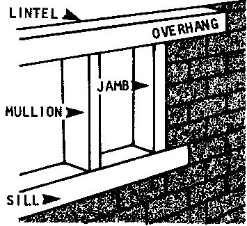
Near the top of the wall, preparations must be made for attaching, and providing support for, the roof.
There are two basic kinds of preparation: wall plates and ring beams. They are built and used in the same way on all block and brick walls.
WALL PLATES
Wall plates are solid, continuous wood beams (usually 5cm x 15cm) that connect the exterior walls of a building along their tops and anchor the roof to the walls. They are essential in all buildings except bamboo structures.
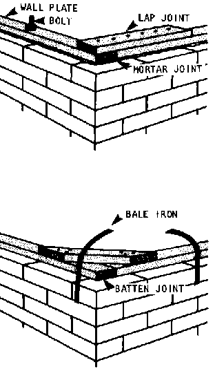
The wall plate can be held in place with 3 devices:
� a good mortar bed, as thick as the horizontal joints in the rest of the structure;
� steel straps (bale iron wire) anchored 1-3 courses below the top of the wall (at least 20cm); place the straps in the appropriate mortar joint every I-1 meter;
� bolts anchored 1-2 blocks or bricks below the top of the wall every 2 meters:
� with small bricks, the bolts can be anchored with a thin metal plate (called a retainer plate) between mortar joints;
� with hollow blocks of whatever size, the bolts can be placed in a core and the core filled with concrete (1:2:4 mix).
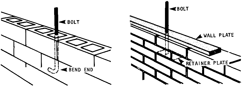
Corner joints of the wall plate may be fastened either with lap joints or batten joints. Battens are slightly stronger.
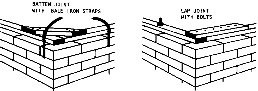
RING BEAMS (ALSO CALLED TIE BEAMS)
A ring beam is a continuous reinforced concrete beam poured in place at the top of concrete block walls only.
Ring beams help the walls resist the outward-spreading pressure from the roof, provide extra reinforcement in earthquake areas, and provide a solid base on which to attach the wall plate.
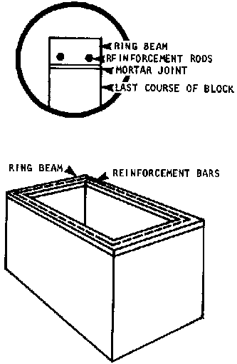
Ring beams are poured in place, so formwork must be attached to the sides of the walls already up.
The beam should be about 15cm deep and exactly as wide as the wall. It should also be reinforced with 2 steel rods 1-1�cm in diameter.
Follow the guidelines for concrete formwork on page 129 and use a 1:2:4 mixture.
To avoid any seams, ring beams must be poured in one continuous operation.
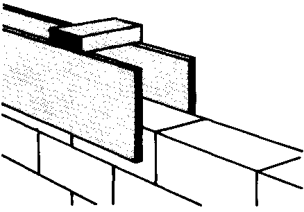
Rammed earth walls are built in layers by packing a damp earth mixture into temporary forms, allowing each layer to dry slightly, and then moving the forms to repeat the process until the walls are as high as planned.
The earth used should be basically the same mixture used for adobe bricks (page 157). However, the proportions of ingredients are not as critical. Large amounts of straw added to the mixture will increase the strength of rammed earth walls significantly.
Only a little water should be added to the earth until it is firm and damp (not muddy).
If a suitable grade of earth can be found, properly damp (after the rainy season), it can be brought directly to the building site and used as-is, or with straw added.
The most manageable size for the forms is 45cm deep by 2 meters long and 37.5-45cm wide, depending on the wall thickness planned.
The forms should be closed on 3 sides: the open side is placed against the previous section of wall. There can't be any spreaders or supports inside the form, so the form's strength comes from battens on the outside held in place with iron straps at the top and flat iron bars at the bottom.
Two special forms should be built for corner sections with alternate long and short sides. These "corner" forms are held together with interlocking iron pins in addition to the strapped battens.
Rammed earth is not very easy to mold or shape once in place, so planning beforehand is essential.
First, mount the formwork on the foundation wall, using iron straps or wire around the battens. Check the form for level and plumb.
Place 10cm of earth in the form and pack it down solidly with a small rod about 4cm in diameter. Use quick, short strokes. The corners must be especially wellpacked.
As much as possible, avoid shaking or vibrating the wall since this tends to loosen the earth.
Add more earth and ram it down until there is a firmly packed layer 30cm deep. Scrape lines about {cm deep in the top surface to give the section some additional "grip".
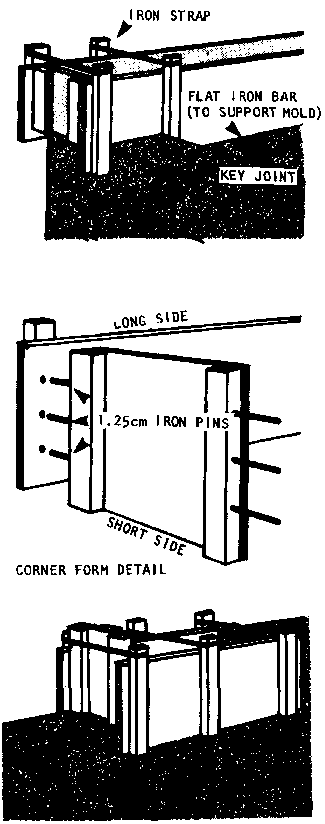
Wait at least an hour before removing the form and starting a new section above the first.
If the earth on top of an old layer has become dry, sprinkle it lightly to dampen it before putting new earth on top of it.
Overlap the corners by alternating short and long legs. This will greatly increase the strength of the walls.
Rammed earth walls can be reinforced. Run a steel band around the entire building just above the door and window level. A second band can be run just below the roof if desired.
To guide the steel band around corners, drive pegs about 20cm long into the rammed earth before removing the form.
Windows and doors are framed according to the same basic procedure followed with adobe brick walls (see pages 164-165). Use wooden sills and lintels about 5cm thick.
First, place the sill in the proper place and press it into the top of the damp earth. Check for level.
Next, place the frame, including the combination head-lintel on the sill, and brace it.
Then place forms on either side of the frame and build the walls up on both sides, checking the frame frequently for plumb.
Finally, before building above the lintel, support it with a temporary brace.
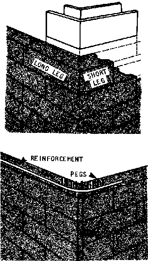
To mount a wood wall plate on the top of a rammed earth wall, place steel rods in the wall about I-1 meter below the top of the wall. Then wrap iron straps around the wall plate and fasten both ends of each strap to the steel rods.
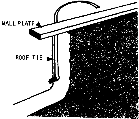
It is a good idea to coat all wood and bamboo roof materials with an anti-termite solution-such as carbonyl, Xylophene, or Creosote.
In areas with very strong winds or storms, it may be advisable to have an experienced local contractor check the roof plan.
To build a flat roof, simply follow the steps below:
� Place the beams across the top of the walls every I-1 meter and lash them securely to the wall-plate with iron straps or staples. Avoid nails through the beams since they may split the wood.
� On the ground, construct the purlins out of sections of 5cm x 10cm wood. Purlin sections should be spliced together, as shown, with the longer piece over the shorter piece. Take care that splices will not be directly over a beam once the purlin is in place. Each completed purlin should be lifted into place and lashed with iron straps to each beam.
� Finally, the roof covering should be attached to the purling. Follow local custom when using materials such as thatch, mud, or tile. Avoid corrugated metal for flat roofs: the metal sheets make buildings very uncomfortable in hot climates and tend to rip off easily in wind.
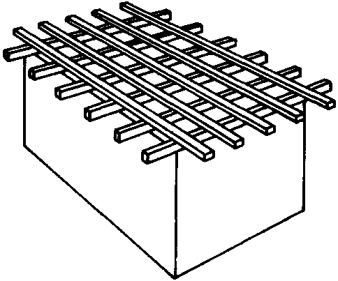
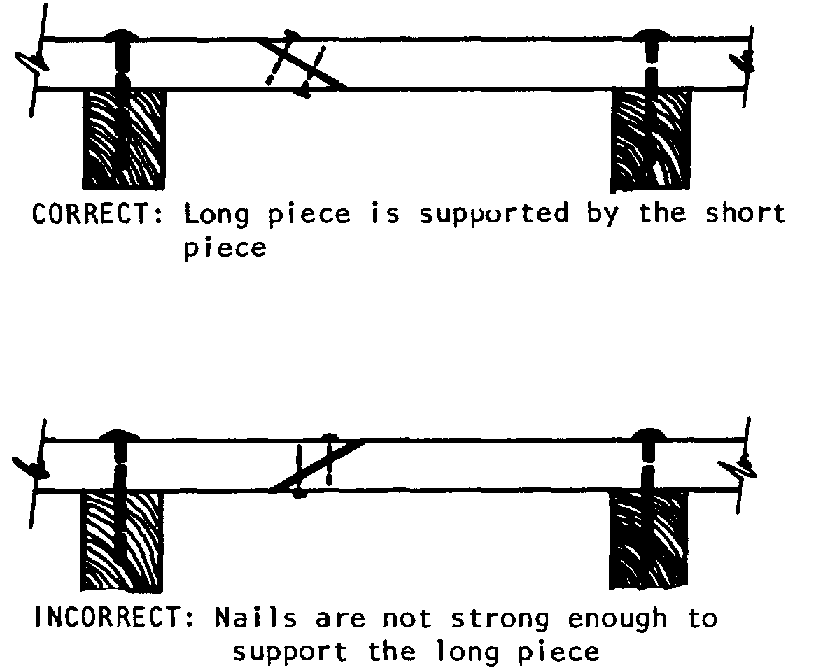
Simple, beam-supported shed roofs for buildings where one wall is built higher than the other are constructed according to the same procedure for flat roofs.
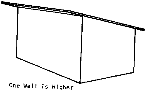
For truss-supported shed roofs, follow these steps:
STEP 1. Place beams across the top of the walls as for flat roofs. However, these beams may be further apart, up to 1.3-1.4 meters, depending on the roof dovering to be used (closer for heavier materials, further for lighter materials). The beams must be as long as the distance between the two walls they will rest on + the overhang planned on each alto.
STEP 2. On the ground, measure and mark off the outline of the truss.
STEP 3. Cut and loosely assemble all the wood sections needed for one truss: the rafter, plus 4 struts. Put stakes firmly in the ground to hold those places in .

STEP 4. Fasten the pieces of the truss together, either by bolting or nailing them.
Whether bolts or nails are used as fasteners, the joints may be made either by overlapping pieces; or, by using single or double plates (separate pieces of wood) to hold the truss members together; or, by splicing. When splicing, use iron straps to reinforce the joint further.
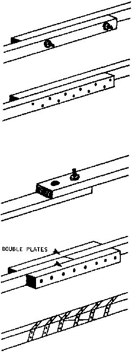
STEP 5. Repeat steps 3 and 4 until a truss has been built for each beam in the roof.
STEP 6. To position the trusses and attach purlins and roof material, follow the instructions for gable roofs below.
To construct a gable roof, follow the steps below:
STEP 1. With a tape measure, mark off the outline of the truss -- the distance from the rafters to the tie beam, from the struts to the tie beam, and so on -- on the ground. Loosely organize the pieces for the first truss along the lines marked and hammer stakes in the ground to hold each member in place.
STEP 2. Check the measurements of the pieces on the ground against the plans and make any needed adjustments; then make sure the stakes are firmly in the ground and won't move.
STEP 3. Assemble the truss with permanent connections as for shed roof trusses using the connections indicated on page 175.
STEP 4. As each truss is assembled, put it up by pushing it over the wall flat, and then raising the point of the truss with a long pole.
STEP 5. Put the end trusses first, bracing them from the ground. Then run a string from apex to apex and align the other trusses with the string.
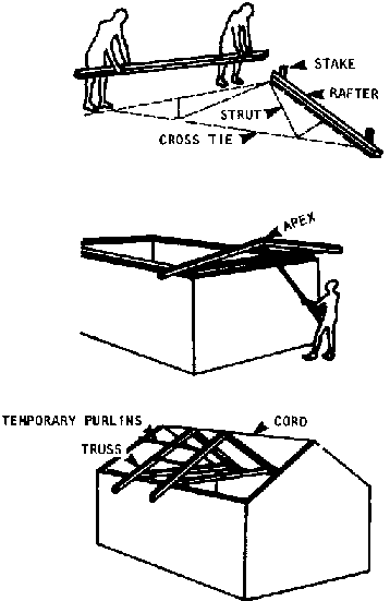
STEP 6. Hold the trusses in place with temporary purlins nailed to each one. Then tie the rafters down to the wall plate with bolts or iron straps.
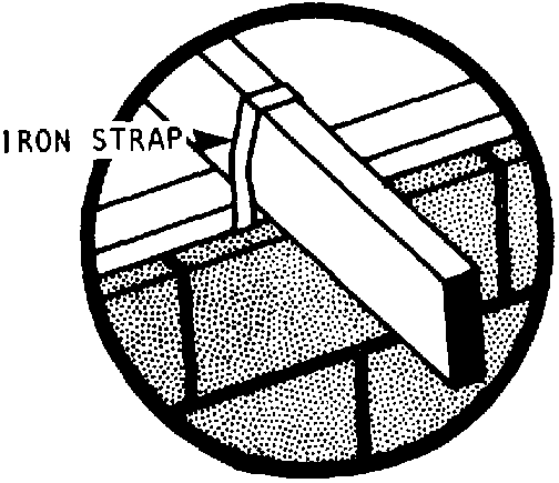
STEP 7. Next, construct the purlins on the ground, rather than on the roof. Stagger the joints in the purlins to avoid sagging in one section of the roof. Be sure that no joints are placed directly over a truss beam: too many nails will split the lumber of the truss.

STEP 8. Attach the purlins to the trusses, starting 20cm from the top of each one. The position of each purlin should be marked in advance by running a string from end-truss to end-truss and placing a nail at the purlin-point on each truss (the nail will keep the purlins from sliding until they have been attached by bolts or iron straps).
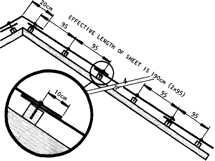
For local roof-covering materials such as tile, mud, or thatch, space the purlins according to local practice. For sheet metal, use the following formula:
Where x = Space between purling,
y = Length of metal sheets, and
10cm = the length each sheet will overlap the one beneath It
X = [Y - 10cm]/2
Example: If 200cm sheeting will be used, the formula would then yield: 200cm - 10cm � 2 = 190cm � 2 = 95cm between each purlin.
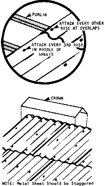
STEP 9. Attach the roof-covering material. Again, follow local practice for local materials.
Corrugated sheets should be attached with specially galvanized large-headed nails through the tops of the curves, not in the valleys, of each sheet.
Nail the sheets through alternate rises wherever the sheets overlap.
Nail them every third rise in the middle of the sheets.
The nailing should begin at the bottom of the end of the roof farthest from the prevailing wind to minimize wind and rain that will blow between the sheets. For example, if the winds come mostly from the east, begin at the lowest part of the western end of the building.
Stagger corrugated metal covering so that each row of sheets covers the joints of the row beneath. Take care also to stagger the nails so they do not form a straight line along any purlin. Such a straight line might split the purlin underneath.
Patch any small holes in the metal with "Masticon" or a gummed metal tape called "Flashband".
STEP 10. Build a crown to cover the top of the roof by cutting metal sheets lengthwise into 3 parts, pounding each part flat, bending it over the ridge of the roof, and nailing it to the metal sheets and purling.
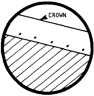
BAMBOO
Bamboo is an excellent building material for several reasons:
� it has a very high strength-to-weight ratio -- very sturdy for such a light-weight material;
� it is easily handled, with little waste and no bark to remove;
� it adapts to a variety of uses; a few bamboo plants in the backyard will provide enough bamboo for a fence, a pigpen, extra rooms, or a house;
� after construction, bamboo can be used for other income-generating crafts such as baskets, mats, and so on.
About the only parts of a building that cannot be made from bamboo are fireplaces and chimneys. However, bamboo is rarely used as the only construction material for a whole building. Usually it is combined with other materials: wood, clay, lime, cement, iron, palm leaves, thatch, and so on.
There are many bamboo species. They differ in thickness, strength, flexibility, and resistance to insects and decay. Each is useful in only a few parts of a building. For example, a species that makes good supporting columns cannot be used to make screen matting for a window. The general characteristics of different species are discussed below. But when in doubt about a specific bamboo supply, the best thing to do is check local practice and/or seek advice from a local contractor.
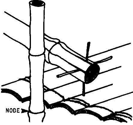
To balance its advantages, bamboo has many drawbacks as a construction material:
� Uneven Dimensions. It is usually necessary to have a large supply in order to weed out pieces that are too thin, too crooked, broken, or otherwise useless.
� Uneven surfaces. Variations in the diameter of the shaft (called a culm), in the prominence of the nodes, and in the rate of tapering at the end of the culm all make certain applications difficult. On the other hand, long culms can often be cut up and the tips used for one purpose while the shafts are used for another.
� Brittleness. In almost all cases bamboo cannot be nailed. Most bonds are made with wire or hemp lashings. A few thick-walled species can be bored to insert pegs.
� Low durability. Bamboo is susceptible to insects (especially beetles and termites) and to rot. Both insect decay and rot can be chemically retarded, and some species are more resistant than others. But even in the best cases, bamboo cannot last much more than 5 years in weight-bearing parts of a building.

Bamboo is basically an above-ground material. Unless it is treated with a preservative, it will last only 2-3 years underground.
However, bamboo will serve as a supporting post: for a house on stilts, for example. Use the largest diameter culms (at least 1220cm) with closely spaced nodes for stiffness. If only smaller shafts are available, they can be bound into columns.
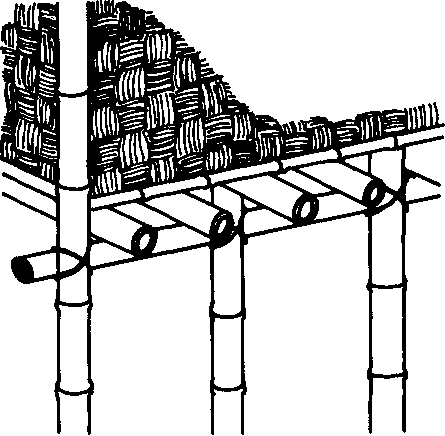
In earthquake areas, bamboo's flexibility makes it a good choice for construction of a frame for floors, walls, and roofs. Such a frame may then be finished by weaving bamboo to form the solid parts of the building, or by using other materials such as clay, mud, or thatch.
Use only whole culms. Cut off and discard the upper, tapered ends of each culm so that all shafts used will have uniform thickness and strength.
The design of a bamboo frame is simple:
Begin with corner posts firmly planted in the corners set out at the site. Next, attach joists (horizontal culms that will support the floor and roof). Then attach studs (vertical culms that will form the wall frame).
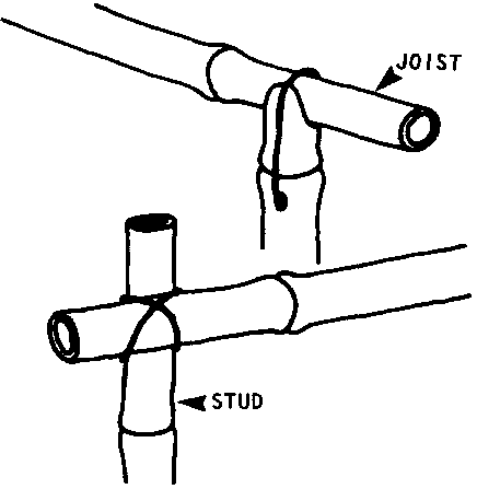
Since bamboo cannot be cut to make perfectly measured joints, the shafts must be lashed with vines, bark' or wire. The only cut that can be made is a notch or cradle-like cut that can be used at the upper end of posts to support a horizontal piece.
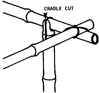
The culm of certain species can be split open and flattened out, making a "board". Among other uses, these boards can be laid directly on a hard earth surface to make a floor. Clay is the best soil for this purpose. It should be evenly graded (for proper drainage) before the boards are pounded into place.
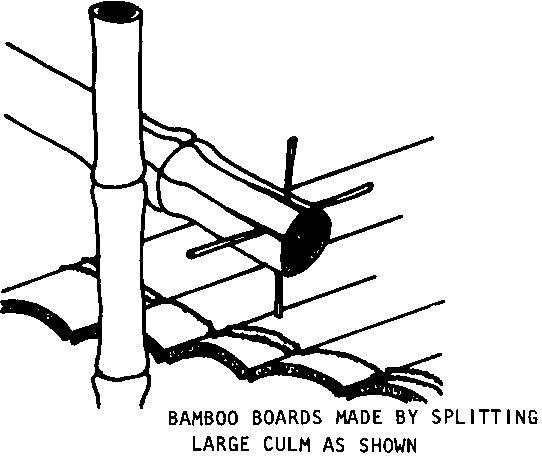
Another type of bamboo floor is raised 1.5-2 meters so that the space underneath may be used for storage of equipment or animals. Thick culms are used as column supports; thinner culms are flattened for the floor; and woven mats are used as floor covering.
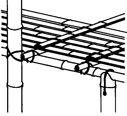
Here are two common ways to use bamboo for walls:
� Wide bamboo shafts are lashed horizontally to both sides of vertical hardwood posts. Occasionally thick bamboo posts are used instead of hardwood posts. The spaces between the bamboo shafts may be filled with mud, mud and stones, thatch, or more bamboo.

� Sprung Strip Construction. Vertical bamboo shafts are woven around three horizontal poles. The frame is then covered with plaster on one or both sides.
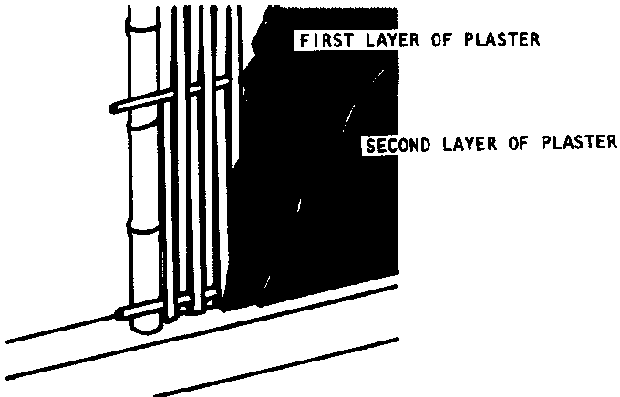
Partitions may be made exactly as walls are but with lighter, portable frames. Use the lightest species available. Crack and flatten the shafts; then weave them into mats that can be suspended.
For practical reasons, doors and windows are kept to a minimum in bamboo housing. Doors tend to be made of:
� wood; or,
� bamboo matting woven on a bamboo frame; or,
� bamboo "bars" put up in a gate-like fashion.
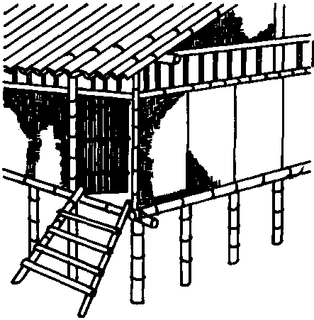
Windows are usually unscreened and covered with bamboo matting or a palm leaf. They can also be made out of a row of shafts tightly pressed and bound together by pieces of wood: this kind of window, when raised, acts as a shade.
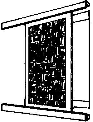
Bamboo is used for the frame of the roof. The roof covering can be of several materials:
� grass thatch;
� corrugated metal or asbestos;
� tile;
� bamboo tiles made from halved culms.
Bamboo can be used to increase the strength of concrete by 2 to 3 times. To be effective, the shafts must be "seasoned" - dried out and shrunk for a month or more and then split in half.
The placement of the shafts is the same as the placement of iron reinforcement rods (see the section on reinforcing concrete, page 137).
The following simple steps will lengthen the useful life of bamboo:
� Cut the shafts at the base and store them upright in clumps in a dry, sheltered place. Never store bamboo out in the open or expose it to rain or dampness: it may rot or be eaten by insects.
� Dust the ends of each shaft with a mixture of 1:20 DDT to talc (or other, safer insecticides where available and effective).
� Use pegs to keep the ends off the ground.
� After 4-8 weeks of drying, trim all twigs and leaves off the shafts and dust the newly cut surfaces.
Latrines
Latrines are vital for community health. They keep local water used for drinking or growing crops free from diseases spread through human feces; and they discourage transmission of diseases by flies that breed in excrement.
In many areas, community acceptance of latrines as an integral part of any home, school, or clinic project may be more important than any other construction ideas in this manual.
Basically, a latrine consists of: a pit dug in the ground for the storage of excrement; a base built over the nit with a small hole in it so that a person can stand over the pit; and a shelter to provide privacy, protect against weather, and to keep flies from breeding in the pit.
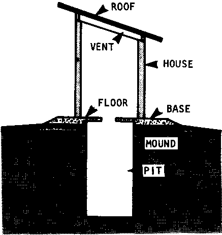
Two principal requirements should govern the choice of a latrine's location:
* It should be close enough to the school, clinic, or home to be reached easily; but far enough away to keep the main building free of odors and potential contamination. 30 meters is the distance recommended by many experts.
* It should be situated so that it will not contaminate ground or surface water that may enter springs, wells, or fields. Satisfying this requirement can sometimes be complex.

The most important considerations to keep in mind are:
� the latrine should be high enough so it will not be flooded during the rainy season;
� the latrine should be downhill from any nearby wells or springs; if this is impossible - of if the land is flat - the latrine must be at least 15 meters away from wells or springs (7.5 meters in sandy soil);
� in regions with fissured rocks or limestone foundations (which can carry pollution great distances), get expert advice!
At the chosen location, begin by digging a pit, either round or square, about 1 meter across, and from 1-3 meters deep. The table below shows recommended depths for a latrine for a family of 5. The same depths may be used for latrines in public buildings such as schools or clinics provided there will be 1 latrine for every 15 people who use the building regularly.
On the table, "wet pit type" refers to pits which penetrate the water table in the ground and are constantly wet. "Dry pit type" refers to pits that are 3 meters or more above the highest underground water level.
If the soil is soft and tends to cave in during the digging, line the pit with stone, brick, wood, or bamboo to keep the sides of the pit strong. Even when the soil is firm, it's a good idea to line the upper few feet.
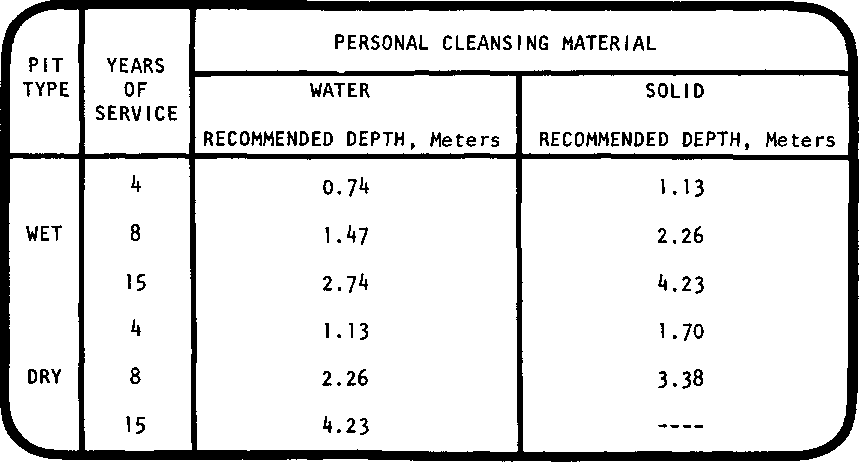
The base is essentially a foundation for the floor. It also helps to prevent hookworm larvae and burrowing rodents from entering the pit.
The best materials for the base are concrete from a 1:2:3 mixture, or stabilized earth with 5-6% cement content. Heavy hewn logs treated for insect resistance may also be used as shown.
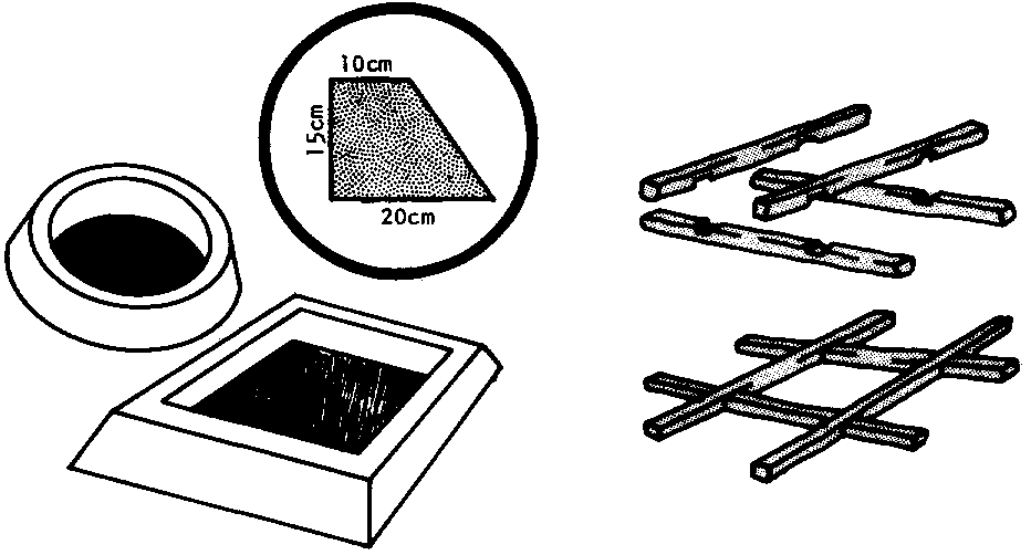
Following construction of the base, a mound of hard-packed earth or dry fill should be built up until it is level with the top of the base (at least 15cm above ground level), and it covers the floor area planned for the shelter.
Above this mound must be placed a floor with a built-in hole about 40cm long and 12-18cm wide. Do not make the hole wider than 18cm or children may fall through it!
The shape of the hole can vary according to local preference. Two common shapes are shown.
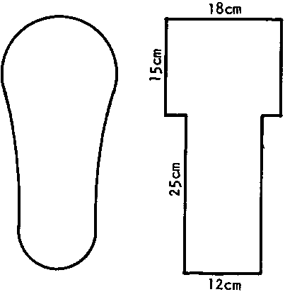
The floor may be built of several materials. Reinforced concrete is best. Build a form about 100cm x 100cm and 6cm deep. Then cut a piece of wood 6cm high and the size and shape of the hole desired. This piece will act as the mold for the hole in the concrete slab. If you slope its sides slightly instead of making them straight up and down, it will be easier to remove from the concrete after the concrete has set.
Place the wood piece inside the 100cm x 100cm form where you want the hole to be. Then place reinforcement rods (bamboo or iron) in a grid across the formwork.
Mix, pour and cure the concrete as you would for any concrete floor (see pages 154-156), After curing, place the concrete slab over the mound and base so that the hole is centered over the pit opening.
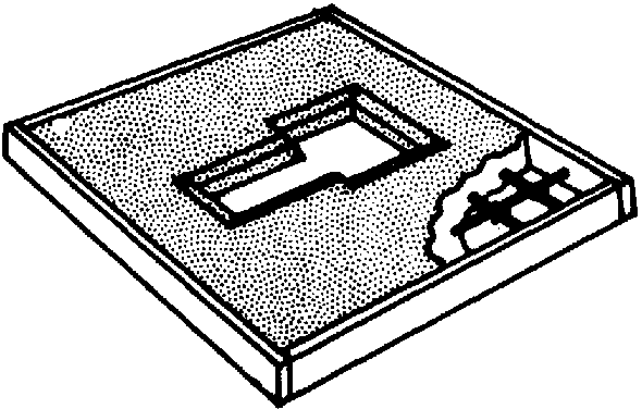
Other materials appropriate for building latrine floors include reinforced brick mortar, wood, and logs with earth.
It may be desirable to add raised foot rests, approximately 30cm long and 10cm wide as shown.
In addition, a simple wood cover can greatly reduce odors and keep flies away from the pit.
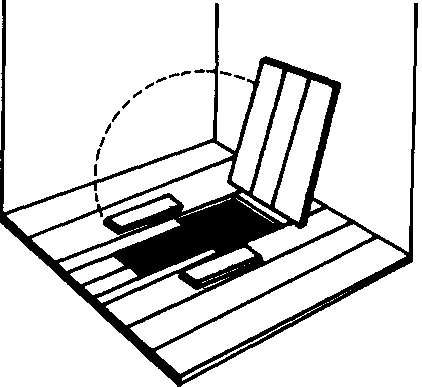
The latrine shelter serves several purposes:
� protection from wind and rain;
� privacy;
� protection of the pit from direct light (darkness keeps flies and other disease-carrying insects and rodents from breeding in the pit).
In general, the shelter should be about 1 meter wide, 1.5 meters long, and 1.5 meters high.
It should have a shed roof with a large overhang [about 60l00cm). The roof should be 10-15cm above the walls for ventilation to diffuse any odors which might build up.
If acceptable socially, it is beat to cut all vegetation within 2 meters of the shelter, especially if food is grown nearby. This will prevent contamination of the ground surface resulting from any possible misuse of the latrine.
The illustrations above show two types of latrine shelter. The actual construction of latrine shelters follows the normal procedures for any building.
One final note: The latrine design described in this manual is only one of the many possible designs. See the sources listed in the bibliography (page 227) for information on other designs.
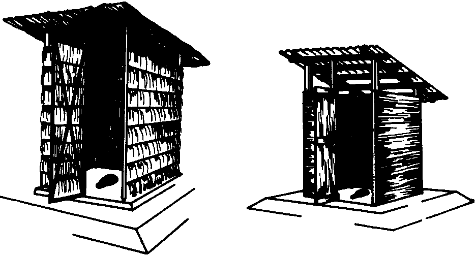
Construction in earthquake areas
In areas where earthquakes or tremors are likely, there are a number of ways to reduce the danger of structural damage and to increase the safety of those who use a building. Special care should be taken in:
� the selection and preparation of the site and the building position;
� the selection of building materials;
� the use of special techniques for reinforcing foundations, floors, walls, and roofs.
One of the simplest precautions against earthquake destruction is to choose a site as far as possible from the fault line. The fault line is the line along which two blocks of earth meet and slide against each other. Earthquakes occur when two such blocks of earth move suddenly.
In areas where a serious earthquake has occurred recently, people near the fault line will know where it is. Fault lines may also be found by looking for places where geological formations such as dry river beds or veins of rock appear to have suddenly split and shifted. The location of such shifts will be on the fault line.

Other suggestions for the selection of a site in earthquake areas include the following:
- Flat terrain is best; avoid sharply sloping ground if possible; ground slippage occurs most often on hills.
- If the land has some slope to it, level the entire site around the building so that the foundation and walls are the same height throughout. Stepped foundations and walls of unequal height are less stable.
- Do not build on "filled-in" earth: it can't be as stable as ground that has settled naturally over time.
- Align the building so that its length is parallel to the nearest fault line. This will help the structure go "with" and not "against" a tremor.
- Choose a site as far from other buildings as possible. The minimum distance between 1story structures should be equal to their height.
- If a new building must be built less than the minimum distance from another building, any separation is better than none. Never interconnect the walls of two buildings.
- Use rectangular or circular shapes for buildings in earthquake areas. Avoid "L-shaped" buildings.
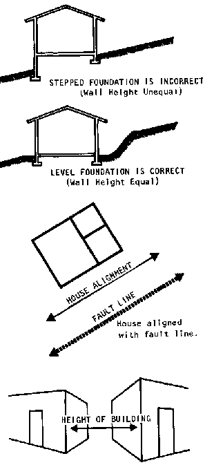
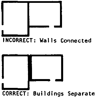
Generally, the safest materials in earthquake areas are the lightest and most flexible.
In foundations concrete footings reinforced with iron or bamboo, and concrete or block foundation walls are good. Avoid rock foundation walls because the large amounts of mortar used to bind the rocks are easily weakened in earthquakes.
For walls, where climate permits, bamboo and wood are the best because their flexibility keeps them from cracking or collapsing, and because they are less dangerous if they do fall. Walls made from bricks or blocks of any material are fine but should be made as light and as thin as possible. Rammed earth walls and rock walls are unstable and dangerous in earthquakes: they should be avoided.
Roofe are safest when made of bamboos and grasses (thatch). Woodbeam supported roofs are also fine, provided the material they support is light, such as shingles or corrugated metal. Adobe and tile roofs should be avoided.
There are many ways of reinforcing buildings to resist earthquakes. The most important and least expensive techniques are listed here. But if earthquakes are a major problem in the local area, the field worker or community should consult experienced local contractors for advice.
All of the techniques listed here can help save a building in an earthquake, whether they are used alone or in any combination. They cannot guarantee that a building will survive a severe earthquake intact. But even in the worst case, they will give people more time to get outside safely, before the building collapses.
To strengthen foundations and floors, reinforce them with bamboo or iron rods.
To strengthen walls:
� place windows and doors on opposite walls;
� place inside doors as close to the middle of interior walls as possible;
� place timber posts at the ends of interior walls (see the section on window and door frames, page 96, for details of construction);
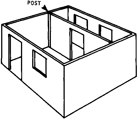
� mount exterior doors so they open to the outside (this permits faster escape during a quake);
� allow at least 1 meter of wall space between openings and corners;
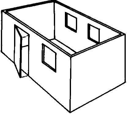
� connect all walls with interlocking wooden beams at the tops of the walls, and preferably at the floor and lintel levels too;
� reinforce wooden frame walls with cross-supports;
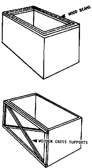
� use a 'tight" bond between brick or block courses; too much mortar will weaken the wall.
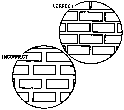
If there is doubt whether the soil at a proposed site will support a building (see page 18) it may be necessary to estimate both the weight of the planned building and the weight-bearing capacity of the soil. This section contains step-by-step directions and tables for both these estimates.
IMPORTANT NOTE: The weight of a planned building cannot be estimated until the builders have decided:
� its size and shape;
� what its walls will be made of and how thick they will be;
� what kind of roof it will have.
CALCULATING A BUILDING'S WEIGHT PER SQUARE METER
Several calculations must be made to estimate a building's weight per square meter. For the purposes of estimation, figure that:
Equation 1.
Weight per square meter = [ weight of longest wall (kg) + weight of roof supported by longest wall (kg) ] / length of longest wall (m)
To find the weight per square meter, therefore, the planner first needs to determine each of the three items on the right side of Equation 1. Follow these steps:
STEP 1. Enter the planned length of the longest wall in Equation 1:
Equation 1.
![]()
STEP 2. Calculate the weight of the longest wall.
Equation 1.
![]()
(a) Use the following equation to determine the weight of the longest wall:
Equation 2
![]()
(b) Use Table A to find the weight per sq. meter for every centimeter of wall thickness of the material with which the building's walls will be built.
|
Table A |
|
|
wall material |
kg/sq. meter per centimeter wall thickness |
|
concrete block |
90 |
|
stabilized earth |
125 |
|
sand-cement block |
75 |
|
adobe |
125 |
|
stone/rock |
150 |
(c) Multiply the number you find in Table A by the thickness of the building's walls. The result will
be the weight of 1 sq. meter of wall; enter it in the correct place in Equation 2:
Equation 2
![]()
(d) Next, multiply the length of the longest wall in meters by its height. The answer will be the number of sq. meters in the wall. Enter this figure in the correct place in Equation
Equation 2
![]()
(e) Compute the weight of the longest wall based on the figures you have entered in Equation 2 in steps 2(c) and 2(d).
STEP 3. Estimate the weight of the roof supported by the longest wall.
Equation 1
![]()
(a) Use the following equation to estimate the weight of the roof supported by the longest wall:
Equation3
![]()
(b) Use Table 8 to find the estimated weight of the roof per sq. meter. If you are in doubt about the roof-style planned, use the figure on the table for flat roofs. Enter the figure you find in Table B in Equation 3:
|
Table B |
|
|
Roof style |
Roof load per sq. m |
|
pitched |
170 kg |
|
flat |
190 kg |
Equation 3
Weight of roof supported by longest wall = weight of roof per sq. meter � number of sq. meters in roof
(c) Next, multiply the length of the roof by its width. If the roof has not been planned yet, assume that it will be 1 meter longer and 1 meter wider than the building. The answer will be the number of square meters in the roof. Enter this figure in the correct place in Equation 3:
Equation 3
![]()
(d) Compute the weight of roof supported by the longest wall using the figures you have entered in Equation 3 in steps 3(b) and 3(c).
STEP 4. Enter the figures you calculated in steps 1, ate), and 3(c) in Equation 1, and calculate the weight of the building per square meter:
Equation 1
![]()
STEP 5. Finally, compare the building's weight per square meter with the weight - bearing capacity of the soil at the site indicated in Table C.
|
Table C |
|
|
Type of soil |
Weight-bearing capacity (kg/sq.m) |
|
Soft, black, drained marsh, or "fill" |
4,900 - 10,000 |
|
Gravel, sand |
29,400 |
|
Hard - packed clay |
58,800 |
|
Rock |
156,000 |
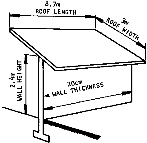
SAMPLE CALCULATION OF A BUILDING'S WEIGHT PER SQUARE METER
Here is a step-by-step sample of how the weight of a building would be estimated, following the procedure outlined on pages 202-205.
Assume that the building pictured above is planned to be 7.5 meters long and 2.4 meters high along its longest wall; assume also that the walls will be made of 20cm thick sand-cement blocks, and that the roof will be 8.7 meters long and 3 meters wide, with a pitched design. If the site selected for the building is soft, dark soil that can support 4,900 kg/sq. meter, can the building be constructed as planned?
Here are the calculations:
Equation 1
Weight per square meter = [ weight of longest wall (kg) + weight of roof supported by longest wall (kg) ] / length of longest wall
STEP 1. Enter the length of the longest wall in Equation 1:
Equation 1
![]()
STEP 2. Calculate the weight of the longest wall.
(a) Use Equation 2:
![]()
(b) Use Table A, page 203, to find the wall's weight per square meter for every centimeter of wall thickness.
The building's walls will be made of sand-cement blocks which Table A says weigh 75 kg/aq. meter for every centimeter of wall thickness.
(c) Multiply the figure you find in Table A by the thickness of the building's walls. The result will be the weight of 1 square meter of wall. Enter this answer in the correct place in Equation 2.
The sand-cement blocks that will be used will be 20cm thick. So a wall made of these blocks will weigh 75 kg/sq. meter x 20cm thick = 1500 kg/square meter.
Entering this answer in Equation 2:
![]()
(d) Multiply the length of the longest wall in meters by its height and enter the result in the correct place in Equation 2.
The longest wall of the building will be 7.5 meters long and 2.4 meters high. 7.5 x 2.4 = 18 square meters.
Entering this answer in Equation 2:
![]()
(e) Compute the weight of the longest wall based on the figures you have entered in Equation 2 in steps 2(c) and 2(d).
1500 kg/sq. meter x 18 sq. meters = 27,000 kg. Entering this result in Equation 1:
![]()
STEP 3. Estimate the weight of the roof supported by the longest wall.
(a) Use Equation 3:
Equation 3
![]()
(b) Use Table B. page 204, to find the estimated weight of the roof per square meter. Enter this figure in the correct place in Equation 3.
The roof is planned with a pitched roof that Table B says will weigh about 170 kg/sq. meter.
Entering this answer in Equation 3:
![]()
(c) Multiply the length of the roof by its height to find the number of square meters of roof space planned. Enter this figure In the correct place in Equation 3.
The roof is planned to be 3 meters wide and 8.7 meters long. am x 8.7m = 26.1 square meters.
Entering this answer in Equation 3:
![]()
(d) Compute the weight of roof supported by the longest wall using the figures you have entered in Equation 3 in steps 3(b) and 3(c).
170 kg/sq. meter x 26.1 sq. meters = 4,437 kg. Entering this result in Equation 1:
![]()
STEP 4. Calculate the weight of the building per square meter, using the figures you calculated in steps 1, 2(e), and 3(c) and Equation 1.
![]()
The building will weigh approximately 4,191 kg/sq. meter.
STEP 5. Compare the building's estimated weight/square meter with the weight-bearing capacity of the soil at the site. Use Table C, page 205.
According to Table C, the weight-bearing capacity of the soft, dark soil at this site is 4,900 kg/sq. meter. Since this building will weigh only 4,191 kg/sq. meter, the building can be built safely at this site.
To determine whether the soil at any proposed site will support a planned building, all the builder needs to do is substitute the figures for his/her building and site in the step-by-step equations on pages 202-205, as shown.
Two kinds of drawings are important aids to help the field worker and community members visualize their foundation plans and check their progress during construction:
� a cross-section view of the footing and foundation wall; and
� a view from above of the footing and foundation wall measurements.
When a community group is ready to begin construction of the foundation, it's a good idea to help them build a small demonstration section of footing and foundation wall that they can use along with these drawings to check their progress. The demonstration section will help everyone see what they have planned to do; at the same time, it will give them practice in the construction techniques and skills they must use on the actual foundation.
DRAWING A CROSS-SECTION VIEW OF THE FOUNDATION
Drawing a cross-section view of the foundation is simple. Here are examples of a cross-section for a rock foundation and for a block foundation wall. Both drawings show concrete footings as well:
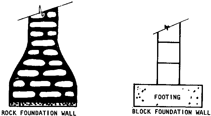
DRAWING FOOTING AND FOUNDATION MEASUREMENTS (VIEW FROM ABOVE)
Drawing the foundation measurements as they would look from above is also simple.
Here are step-by-step instructions for drawing the foundation measurements of a sample building:
1. Draw a solid line representing the outside dimensions of the walls of the building, This line will also represent the outside dimensions of the foundation wall.
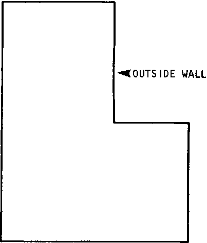
2. Draw a second solid line inside the first one to represent the inside dimensions of the building's walls. This line will also represent the inside dimensions of the foundation wall. The space between the two lines should be exactly the width of the planned walls to scale.
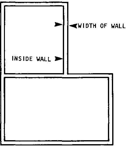
3. Subtract the width of the wall from the planned width of the foundation footing. Divide the remainder in two and convert the answer into the scale dimension being used in the drawing. This figure represents the distance between the inner side of the wall and the inner side of the foundation footing.
4. Draw a dotted line inside the drawing of the walls. This line represents the inner dimension of the footing. The space between it and the inside solid line (step #2) should be exactly the distance calculated in step #3.
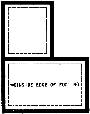
5. Draw a dotted line outside the drawing of the walls. This line represents the outer dimension of the footing. The space between it and the outside solid line (step #1) should be exactly the distance calculated in step #3.
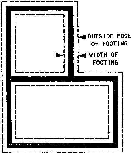
6. On either side of the drawing's length, add a solid line exactly as long as the longest wall (that is, the longest outer solid line).
7. On either side of the drawing's width, add a solid line exactly as long as the longest wall (that is, the longest outer solid line).
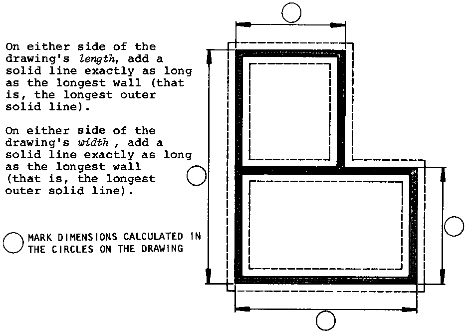
8. Place a mark along each line from steps #6-7 wherever the outer wall turns a corner. Indicate the actual length of each straight section of wall.
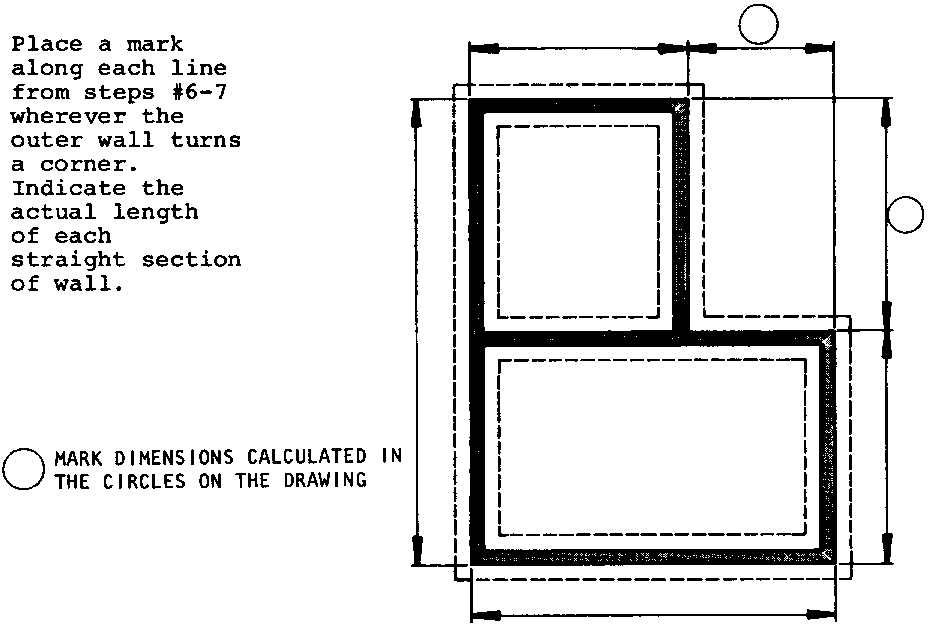
9. Outside the lines drawn in steps #6-7, draw two more solid lines exactly as long as the length and width of the outer dotted line. Mark these lines to indicate the actual length of each straight section of foundation footing.
10. Underneath the completed drawing, write down what the footing and foundation wall will be made of and their cross-section dimensions.
11. The completed drawing is an actual scale drawing showing the trenches that must be dug for the footing and the dimensions of the foundation walls.
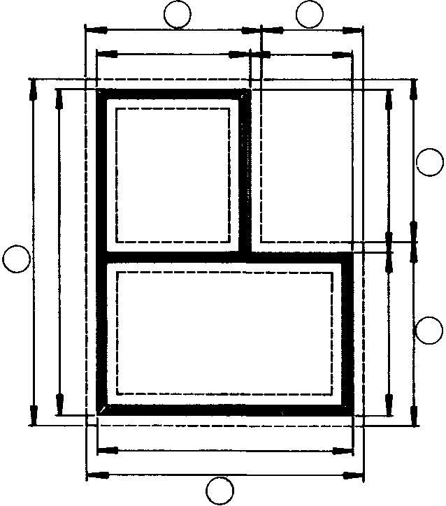
To estimate the amount of concrete needed for a floor, use the following equation and table:
Equation
![]()
Table. SUGGESTED THICKNESS OF CONCRETE FLOORS
|
Purpose of Floor |
Thickness (m) |
|
School, Clinic, House |
.100 |
|
Garage (for vehicles) |
.125 |
|
Farm storage (heavy equipment) |
.150 |
STEP 1. Find the thickness of the concrete layer that should be used for your building in the table, Enter this figure in the Equation:
STEP 2, Multiply the length of your building by its width to find out what floor space it will have. Enter this figure in the Equation:
![]()
STEP 2. Multiply the length of your building by its width to find out what floor space it will have. Enter this figure in the Equation:
Cubic meters of concrete needed for floor = thickness of concrete layer (m) x floor area (sq. meters)

In cases where the building will not be a simple rectangle, the total floor area can be determined by multiplying the length and width of each separate room and then adding the areas of all rooms together.
Sample Calculation:
|
Floor area Room 1 |
= 2m x 2.0m |
= 4.0 sq. m |
|
Floor area Room 2 |
= 1m x 1.5m |
= 1.5 sq. m |
|
Floor area Room 3 |
= 1m x 1.0m |
= 1.0 sq. m |
|
Total Floor Area |
= 6.5 sq. m |
In round buildings, the floor area will be the radius of the building squared times 3.14. The radius is the distance from the outside of a circle to its center.
Sample Calculation:
|
Floor Area |
= Radius (2m) x Radius (2m) x 3.14 |
|
= 4 sq. meters x 3.14 |
|
|
= 12.56 sq. meters |
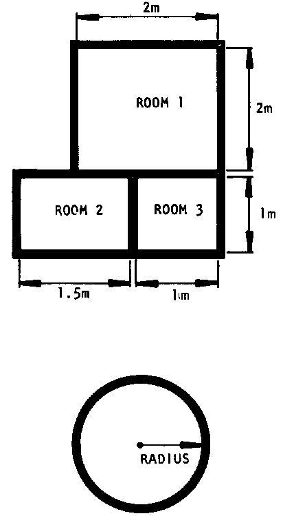
STEP 3. Enter the answers you found in steps 1 and 2 in the Equation and multiply them. The answer will represent the number of cubic meters of concrete that must be purchased or made for the floor.
Sample Calculation (using figures for round clinic shown above)
|
Cubic meters of concrete needed for floor |
= thickness of concrete layer (m) � floor area (sq. meters ) |
|
= .10m x 12.56 sq. meters |
|
|
= 1.256 cubic meters |
This section gives step-by-step directions for calculating the materials needed to build three types of wall: poured concrete, rammed earth, and brick/block.
POURED CONCRETE AND RAMMED EARTH
To determine how much poured concrete or rammed earth he/she needs, the builder must calculate how many cubic meters of material it will take to "fill" the wall space.
Use the following equation:
Equation .
Cubic meters of material needed for one wall = thickness of wall (meters) � wall area (sq. meters)
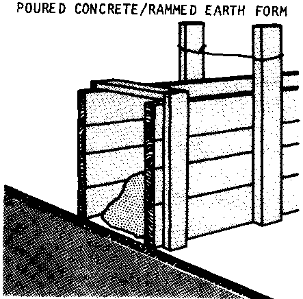
STEP 1. Decide how thick the wall will be (see page 34 for a discussion of what to consider when planning wall thickness}. Enter this figure in the correct part of the equation.
STEP 2. Calculate the wall area in square meters by multiplying the wall's length by its width.
STEP 3. Multiply the answers you found in steps 1 and 2. The result will be the cubic meters of concrete or rammed earth you will need to build that one wall.
STEP 4. Repeat steps 1 through 3 for each wall of the building.
STEP 5. Add the cubic meters of concrete or rammed earth needed for all the walls of the building. The result will be the total number of cubic meters of concrete or rammed earth you will need for the building.
Calculating Bags of Cement Needed for a Concrete Wall
Builders who plan to purchase the cement for their concrete need to know how many sacks or bags of cement to buy. Once you have determined how many cubic meters of concrete you will need, finding the number of bags of cement is easy: just look the answer up in Table 3, in Appendix 4 (page 222). To use the table, first, find the concrete mixture you plan to use. In the case of walls, the mixture would be 1:2 3/4 :4 The table will then tell you how many cubic meters of concrete you will get from one sack of cement. Divide the number of cubic meters of concrete you plan to use by the amount you would get from one sack. The answer will be the number of sacks of cement you need to purchase.
Calculating Wheelbarrowsful of Rammed Earth or Concrete Needed
Many builders want to know how many wheelbarrows full of concrete or rammed earth they must bring to the construction site for wall construction: this information gives them an idea of how much work will be involved.
The number of wheelbarrowsful needed can be estimated by following these steps:
� Build a form exactly 1 cubic meter in size and count how many wheelbarrowsful of rammed earth or concrete it takes to fill the form.
� Multiply this number by the total cubic meters of material that are needed for construction (from Step 5, page 216). Your answer will tell you how many wheelbarrowsful are needed.
BLOCK AND BRICK WALLS
To estimate the number of blocks or bricks needed to build a wall, follow these steps:
STEP 1. Calculate the wall area in square meters by multiplying the wall's length by its width.
STEP 2. Note down the nominal size of the block face. The nominal face of a block is the height and length of the block surface visible in the wall after the block is laid.
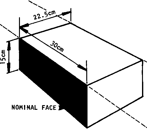
STEP 3. Use the table below to find how many blocks or bricks of the size you plan to use are needed to build 1 square meter of wall surface.
APPROXIMATE NUMBER OF BLOCKS OR BRICKS REQUIRED TO BUILLD 1 SQUARE METER WALL SURFACE
|
Nominal Size of Face (cm) |
Number of Blocks or Bricks Needed |
|
7,5 x 20 |
65 |
|
10.0 x 30 |
32,5 |
|
13.25 x 30 |
25 |
|
15,0 x 30 |
22 |
|
20,0 x 30 |
16,5 |
|
15,0 x 40 |
16,5 |
|
20.0 x 40 |
12,5 |
|
15,0 x 60 |
11 |
STEP 4. Multiply the number you found in the table by the number of square meters of wall surface you found in step 1, The result will be the approximative number of blocks or bricks needed to build the wall,
Sample Calculation:
How many blocks would it take to build a wall with 17 square meters surface area using blocks with a nominal face 15cm x 30cm?
The table shows that 22 15cm x 30cm blocks are needed to build 1 square meter of wall area.
17 sq. meters x 22 blocks/sq. meter = 374 blocks
STEP 5. Repeat steps 1 through 4 for each wall of the building and add the results. The total will represent the number of blocks or bricks you must buy or make for the walls.
Note: Any estimate of the number of blocks/bricks needed for a building's walls arrived at through this method will include extra blocks, since the space taken by window and door openings is treated as though it were filled in with blocks. Generally it is a good idea to buy or make these extra blocks. This will give you a margin of error for wasted or broken blocks.
Calculating Mortar Quantities
The amount of mortar needed to bond the blocks/bricks for a building depends on the number of blocks/bricks and their size. To calculate the amount of mortar needed for lam thick mortar joints, follow these steps:
� Divide the number of blocks needed for the building by 100, For example, if the building requires 1,536 blocks, 1536 . 100 = 15.36.
� Use the table below to find the cubic meters of mortar needed to lay 100 blocks. For example, if the nominal size of the blocks used will be 10cm x 20cm x 40cm, .073 cubic meters of mortar would be needed to lay every 100 blocks.
� Multiply the answers found in the above steps. For example, if 1,536 blocks of nominal size 10cm x 20cm x 40cm are needed for a building's walls, multiply 15.36 x .073. 15.36 x .073 = 1.12 cubic meters of mortar. Table 7 in Appendix 5 (page 224) may be used to determine how much cement, lime, and sand you will need to make the mortar required for any building.
QUANTITIES OF MORTAR REQUIRED TO LAY 100 BLOCKS/BRICKS (Mortar for Joints 1cm Thick Including 25% Allowance for Waste)
|
Nominal Size of Blocks/Bricks (cm) |
Cubic Meters of Mortar |
|
10 x 13,25 x 30 |
.053 |
|
15 x 13,25 x 30 |
.053 |
|
20 x 13,25 x 30 |
.067 |
|
10 x 15 x 30 |
.065 |
|
15 x 15 x 30 |
.065 |
|
20 x 15 x 30 |
.070 |
|
10 x 20 x 30 |
.061 |
|
15 x 20 x 30 |
.061 |
|
20 x 20 x 30 |
.076 |
|
10 x 20 x 40 |
.073 |
|
15 x 20 x 40 |
.073 |
|
20 x 20 x 40 |
.092 |
|
25 x 20 x 40 |
.092 |
|
30 x 20 x 40 |
.092 |
|
15 x 15 x 60 |
.092 |
|
20 x 15 x 60 |
.115 |
|
25 x 15 x 60 |
.115 |
|
30 x 15 x 60 |
.115 |
TABLE 1
|
Recommended |
Thickness of Concrete Slabs (cm) |
|
Basement floors for dwellings |
10 |
|
Porch floors |
10-12.5 |
|
Stock barn floors |
12.5-15 |
|
Poultry house floors |
10 |
|
Hog house floors |
10 |
|
Milk house floors |
10 |
|
Granary floors |
12.5 |
|
Implement shed floors |
15 |
|
Tile floor bases |
6.25 |
TABLE 2
Quantities of Materials Required to Build One Cubic Meter of Concrete (for Aggregates 2.5 Centimeters or Less)
|
Mixtures |
Barrels of Cement |
Cubic Meters of Sand |
Cubic Meters of Stone |
|
1:1:1� |
3.56 |
.40 |
.60 |
|
1:1:2 |
3.23 |
.36 |
.73 |
|
1:1:2� |
2.90 |
.33 |
.81 |
|
1:1:3 |
2.64 |
.30 |
.89 |
|
1:1�:2 |
3.04 |
.43 |
.68 |
|
1:1�:3 |
2.44 |
.42 |
.84 |
|
1:13/4:2 |
2.75 |
.54 |
.62 |
|
1:1 3/4:2� |
2.64 |
.51 |
.67 |
|
1: 1 3/4:2 3/4 |
2.44 |
.47 |
.80 |
|
1:2:3 |
2.24 |
.50 |
.77 |
|
1:2:3� |
2.07 |
.48 |
.83 |
|
1:2:4 |
1.95 |
.44 |
.88 |
|
1:2:5 |
1.73 |
.39 |
�97 |
|
1 :2�:2� |
2.32 |
.59 |
.65 |
|
1 :2�:3 |
2.18 |
.55 |
.74 |
|
1 :2�:4 |
1.91 |
.48 |
.86 |
|
1:2�:5 |
1.68 |
.42 |
.94 |
|
1:2�:3 |
2.11 |
.59 |
.71 |
|
1 :2�:3� |
1.98 |
.56 |
.78 |
|
1:2�:4 |
1.82 |
.51 |
.82 |
|
1:2�:4� |
1.82 |
.48 |
.87 |
|
1:2�:5 |
1.62 |
.46 |
.91 |
|
1:2 3/4 ;4 |
1.74 |
.54 |
.79 |
|
1:3:4 |
1.66 |
.56 |
.75 |
|
1:3:5 |
1.49 |
.51 |
.84 |
|
1:3:6 |
1.36 |
.46 |
.92 |
TABLE 3
Volume of Concrete Construction per Sack of Cement (for Aggregates Not Larger than 2.5
Centimeters)
|
Concrete Mixtures |
Cubic Meters of Concrete Per Sack of Cement |
Concrete Mixtures |
Cubic Meters of Concrete Per Sack of Cement |
|
1:1:1� |
.07 |
1:2�:2� |
.10 |
|
1:1:2 |
.08 |
1:2�:3 |
.12 |
|
1:1:2� |
.09 |
1:2�:4 |
.13 |
|
1:1:3 |
.10 |
1:2�:5 |
.15 |
|
1:1�:2 |
.08 |
1:2�:3 |
.12 |
|
1:1�:3 |
.10 |
1:2�:3� |
.13 |
|
1:1 3/4:2� |
.10 |
1:2�:4 |
.14 |
|
1:1 �:2� |
.10 |
1:2�:4� |
.15 |
|
1:1 3/4:2 3/4 |
.10 |
1:2�:5a |
.15 |
|
1:2:3 |
.11 |
1:2:3/4:4 |
.14 |
|
1:2:3� |
.12 |
1:3:4 |
.14 |
|
1:2:4 |
.13 |
1:3:5 |
.17 |
|
1:2:5 |
.14 |
1:3:6 |
.18 |
TABLE 4
Suitable Mixtures for Various Concrete Construction Projects
|
Concrete Mixture |
|
|
Floors |
|
|
. One Course |
1:1 3/4:4 |
|
. Heavy Duty, One Course |
1:1:2 |
|
. Farm Buildings |
1:2�:3 |
|
Foundation Walls and Footings |
1:2 3/4:4 |
|
Basement Walls |
1:2�:4 |
|
Tanks |
1:2:3 |
|
Fence Posts |
1:1:1� |
|
Retaining Walls |
1:2:3� |
|
Barnyard Pavements |
1:3:5 |
|
Lintels |
1:2:4 |
|
Beam Filling |
1:3:4 |
|
Silo Pits |
1:2�:3 |
|
Steps |
1:2�:3 |
TABLE 5
Approximate Number of Bricks Required to Build 10 Square Meters of Exterior Wall Surface
(Mortar joints 1.25cm thick)
|
Wall Thickness (cm) |
(Nominal) Size of Brick (cm) |
|||
|
6.5 x 10 x 20 |
7.5 x 10 x 20 |
10 x 10 x 20 |
5.6 x 9.4 x 20 |
|
|
10 |
730 |
650 |
485 |
665 |
|
20 |
1455 |
1300 |
970 |
1330 |
|
30 |
2075 |
1950 |
1455 |
1995 |
|
40 |
2910 |
2600 |
1940 |
2660 |
TABLE 6
Mortar Required to Lay 1000 Bricks With 1.25cm Mortar Joints (10% Allowance for Waste Included)
NOMINAL SIZE OF BRICK: 10cm x 6.5cm x 20cm 10cm x 7.5cm x 20cm 10cm x 10cm x 20m
WALL THICKNESS
|
10cm* |
.32 cu. meters |
.33 cu. meters |
.36 cu. meters |
|
20cm |
.42 cu. meters |
.44 cu. meters |
.50 cu. meters |
|
30cm** |
.45 cu. meters |
.47 cu. meters |
.55 cu. meters |
* Figures for 10cm thick walls include mortar for bed and end Joints only.
** Figures for 20cm and 30cm thick walls include bed and end joint mortar plus mortar for the vertical joints needed in double brick walls.
TABLE 7
Materials Required To Make 0,10 Cubic Meters of Mortar
|
Mortar Mixtures By Volume 1 part cement |
50kg Sacks of Cement |
25kg Sacks of Hydrated Lime or Clay Mortar |
Cubic Meters of Sand |
|
� part clay mortar |
9.79 |
4.11 |
0.75 |
|
3 parts sand |
|||
|
1 part cement |
|||
|
� part hydrated lime |
7.93 |
1.33 |
0.64 |
|
3 parts sand |
|||
|
1 part cement |
|||
|
1 part hydrated lime |
4.23 |
2.89 |
0.69 |
|
6 parts sand |
|||
|
1 part masonry cement |
8.73 |
0.68 |
|
|
3 parts sand |
LENGTH
1 meter (m) = 39.37 inches = 3.28 feet = 1.31 yards
1 centimeter (cm) = 0.01 meters = 0.3937 inches
1 foot = 0.3048 meters
1 yard = 0.9144 meters
1 inch = 2.54 centimeters
AREA
1 square meter = 10.76 square feet
(sq. m)
1 square foot = 0.3048 sg. Meters = 929 sq. centimeters
VOLUME
1 cubic meter = 1.308 cubic yards
(cu. m)
1 cubic yard = 0.7646 cu. meters
WEIGHT
1 kilogram (kg) = 2.2046 pounds
1 pound = 0.4536 kilograms
NOTE: Wherever possible, the address through which copies of the following sources may be obtained has been listed. Several manuals are unpublished material that may only be found in Peace Corps files. Questions about these materials should be sent to:
Peace Corps
Information Collection & Exchange
806 Connecticut Avenue, N.W.
Washington, D.C. 20525
USA
BAMBOO:
1. McClure, F.A., Bamboo as a Building Material. U.S. Dept. of Agriculture, Foreign Agriculture Service, 1970. Write to:
Dept. of Housing and Urban Affairs
Division of International Affairs
Washington, D.C. 20410 USA
2. United Nations Dept. of Economic and Social Affairs. The Use of Bamboo and Reeds in Building Construction. Publication ST/SOA/113. Refer to sales # E.72.IV.3 and write to:
United Nations Sales Section
New York, New York USA
CONCRETE CONSTRUCTION AND REINFORCED CONCRETE COLUMNS:
3. Brann, Donald R. Concrete Work Simplified, Revised Edition, Directions Simplified, Inc., 1971. Write to:
Directions Simplified, Inc.
Easi-Build Pattern Co., Inc.
529 North State Road
Briarcliff Manor, New York 10510 USA
4. Dalzell, James Ralph and Gilbert Townsend. Concrete Block Construction for Home and Farm. American Technical Society, Chicago, 1957. Write to:
American Technical Society
5608 Stony Island Avenue
Chicago, Illinois 60637 USA
5. Davies, John Duncan. Structural Concrete. MacMillan and Co., New York, 1964. Write to:
MacMillan Publishing Co., Inc.
Riverside, New Jersey 08075 USA
6. Gibson, J. Herbert. Concrete Design and Construction. American Technical Society, Chicago, 1951. Write to same address as #4 on page 226.
7. Putnam, Robert. Concrete Block Construction, 3rd Edition. American Technical Society, Chicago, 1973. Write to same address as #4 on page 226.
8. Randall, Frank A. Jr. and William C. Panarese. Concrete Masonry Handbook. Portland Cement Association, 1976. Write to:
Portland Cement Association
Old Orchard Road
Skokie, Illinois 60076 USA
9. Waddell, Joseph J. Concrete Construction Handbook, 2nd Edition, McGraw Hill Co., New York, 1974. Write to:
McGraw Hill Book Co.
1221 Avenue of the Americas
New York, New York 10036 USA
10. Winter, George. Design of Concrete Structures, 8th Edition. McGraw Hill Co., New York 1972. Write to same address as #9 above.
FOUNDATIONS AND FOUNDATION DESIGNS:
11. Brann, Donald R. Forms, Footings, Foundations, Framing. Directions Simplified, Inc., 1974. Write to same address as #3, page 226.
12. Carson, Arthur Brinton. Foundation Construction. McGraw Hill Co., New York, 1965. Write to same address as #9 above.
13. Chellis, Robert Dunning. Pile Foundations, 2nd Edition. McGraw Hill Co., New York, 1961. Write to same address as #9 above.
14. Ulrey, Harry R. Carpenters and Builders Library: Layouts, Foundations, Framing. Theodore Audel & Co., Indiannapolis, 1974. Write to:
Bobb-Merrill Co. Inc.
4300 West 62nd Street
Indiannapolis, Indiana 46268 USA
BLOCK AND BRICK CONSTRUCTION {MASONRY):
15. Boudreau, Eugene H. Making the Adobe Brick. Fifth-Street Press, New York, 1971. Write to:
Bookworks
Random House, Inc.
457 Hahn Road
Westminster, Maryland 21157 USA
16. Busch, Lawrence. Construction With Pressed Earth Block (Togo). Peace Corps: write to address on top of page 226.
17. Dalzell, J. Ralph. Simplified Masonry Planning and Building. McGraw Hill, New York, 1953. Write to same address as #9 above.
18. Dixon, Michael. Field Manual for Production of Bricks in a Rural Area (Pakistan). Peace Corps: write to address on top of page 226.
19. Frankly, Lee. The Masonry House: Step-by-Step Construction in Tile and Brick. Duell, Sloan, and Pearce, New York, 1950. No address available.
20. Ray, J. Edgar. Revised by Harold V. Johnson. The Art of Bricklaying. Charles A. Bennett Co., 1971. Write to:
Charles A. Bennett Co., Inc.
809 West Detweiller Drive
Peoria, Illinois 61614 USA
21. U.S. Dept. of Agriculture. Building With Adobe and Stabilized Earth Blocks. Dept. of Agriculture Leaflet No. 2535. Write to U.S. Dept. of Agriculture, Independence Avenue, Washington, D.C. N.W. USA
WOOD-FRAME CONSTRUCTION:
22. Anderson, Leroy Oscar. How to Build a Wood-Frame House. Dover Press, 1973. (Reissue of the revised 1970 Edition of the U.S. Dept. of Agriculture Handbook No. 73, originally pulbished by Government Printing Office under the title of Wood-Frame House Construction.) Write to same address as #21 above, or to:
Dover Publications, Inc.
180 Varick Streeet
New York, New York 10014 USA
23. Anderson, Leroy Oscar. Low-Cost Wood Homes for Rural America: Construction Manual. U.S. Dept. of Agriculture Handbook No. 364. Write to same address as #21 above.
24. Blackburn, Graham. Illustrated Housebuilding. Overlook Press, 1974. Write to:
Overlook Press
c/o Viking Press
625 Madison Avenue
New York, New York 10022 USA
25. Brann, Donald R. How to Build an Addition. Directions Simplified, Inc., 1975. Write to same address as #3, page 226.
LATRINES:
26. Karlin, Barry. Thailand's Water-Seal Privy Program: A Procedural and Technical Review. U.S.O.M., Korat, Thailand. Write to the Peace Corps at the address on top of page 226, or to the author at:
American Public Health Association
1015 18th Street, N.W.
Washington, D.C. USA
27. Wagner, Edmund G. and J.N. Lanoix. Excreta Disposal for Rural Areas and Small Communities. World Health Organization, Geneva, 1958. Write to:
Q Corporation
49 Sheridan Avenue
Albany New York, 12210
ORGANIZATION AND MANAGEMENT OF SELF-HELP CONSTRUCTION GROUPS:
28. Peace Corps (Jamaica). Manual for Supervising Self-Help Home Construction with Stablilized Earth Blocks. Write to address on top of page 226.
29. Warner, Jack R. Handbook of Construction: Peace Corps Training Manual. Longmans Green and Co., London. Write to address on top of page 226.
ESTIMATING CONSTRUCTION MATERIALS AND COSTS:.
30. Cooper, F. Building Construction Estimating. McGraw Hill Co., 1959. Write to same address as #9 on page 227.
GENERAL CONSTRUCTION
31. Alcock, A.E.S. and Richards. How to Build: Setting Out. Longmans Co., London, 1960. Write to:
Longmans, Inc.
19 West 44th Street
Suite 1012
New York, New York 10036 USA
32. East Pakistan (Bangladesh) Public Works. Building Design Manual. Dacca, 1965. Write to address on top of page 226.
33. Fullerton, Richard L. Building Construction in Warm Climates, Volumes 1 and 2. Oxford Tropical Handbooks, Oxford University Press, London, 1967. Write to:
Oxford University Press, Inc.
200 Madison Avenue
New York, New York 10016 USA
34. Intermediate Technology Group. Intermediate Technology Series: Manual on Building Construction. Parnell House, London. Write to:
Intermediate Technology Group
Parnell House
London, ENGLAND
35. Peace Corps (Togo). Construction Handbook: In-Country Training. Peace Corps, 1974. Write to address on top of page 226.
36. Ulrey, Harry F. Carpenters and Builders Library: Tools, Steel Square, Joinery. Theodore Audel & Co., Indiannapolis, 1974. Write to same address as #14, page 227.
37. U.S. Dept. of Housing and Urban Development, Office of International Affairs. Como Fabricar Una Casa Usanda. Tecnica Ayuda Propia. Government Printing Office, 1974. Write to same address as #1, page 226, or to:
U.S. Government Printing Office
North Capitol Street, N.W.
Washington, D.C. USA